
Fuel cell power plant warm up

a fuel cell power plant and fuel cell technology, applied in the direction of electrochemical generators, lighting and heating apparatus, combustion types, etc., can solve the problems of insufficient temperature rise of combustion gas and corresponding time difference, and achieve the effect of lengthening the time required for warming up the fuel cell power plan

Inactive Publication Date: 2009-01-13
NISSAN MOTOR CO LTD
View PDF11 Cites 2 Cited by
  • Summary
  • Abstract
  • Description
  • Claims
  • Application Information

AI Technical Summary

Benefits of technology

[0004]When this warm up device is used, however, the burner first warms up the reformer using the heat generated by fuel combustion, and thus the temperature of the combustion gas does not rise sufficiently until warming up of the reformer is complete. As a result, a commensurate time difference occurs between the completion of reformer warm up and the completion of carbon monoxide removal device warm up using combustion gas heat. This time difference is responsible for lengthening the time required for warming up the fuel cell power plant.
[0005]It is therefore an object of this invention to reduce the amount of time required for warming up an entire fuel cell power plant by eliminating discrepancies in the amount of time required to warm up each reactor which uses a catalyst.
[0006]It is a further object of this invention is to reduce the amount of energy expended in the warming up of reactors using catalysts.

Problems solved by technology

When this warm up device is used, however, the burner first warms up the reformer using the heat generated by fuel combustion, and thus the temperature of the combustion gas does not rise sufficiently until warming up of the reformer is complete.
As a result, a commensurate time difference occurs between the completion of reformer warm up and the completion of carbon monoxide removal device warm up using combustion gas heat.

Method used


Image

  • Fuel cell power plant warm up
  • Fuel cell power plant warm up
  • Fuel cell power plant warm up

Examples


second embodiment

[0088]this invention will now be described with reference to FIGS. 6 and 7.

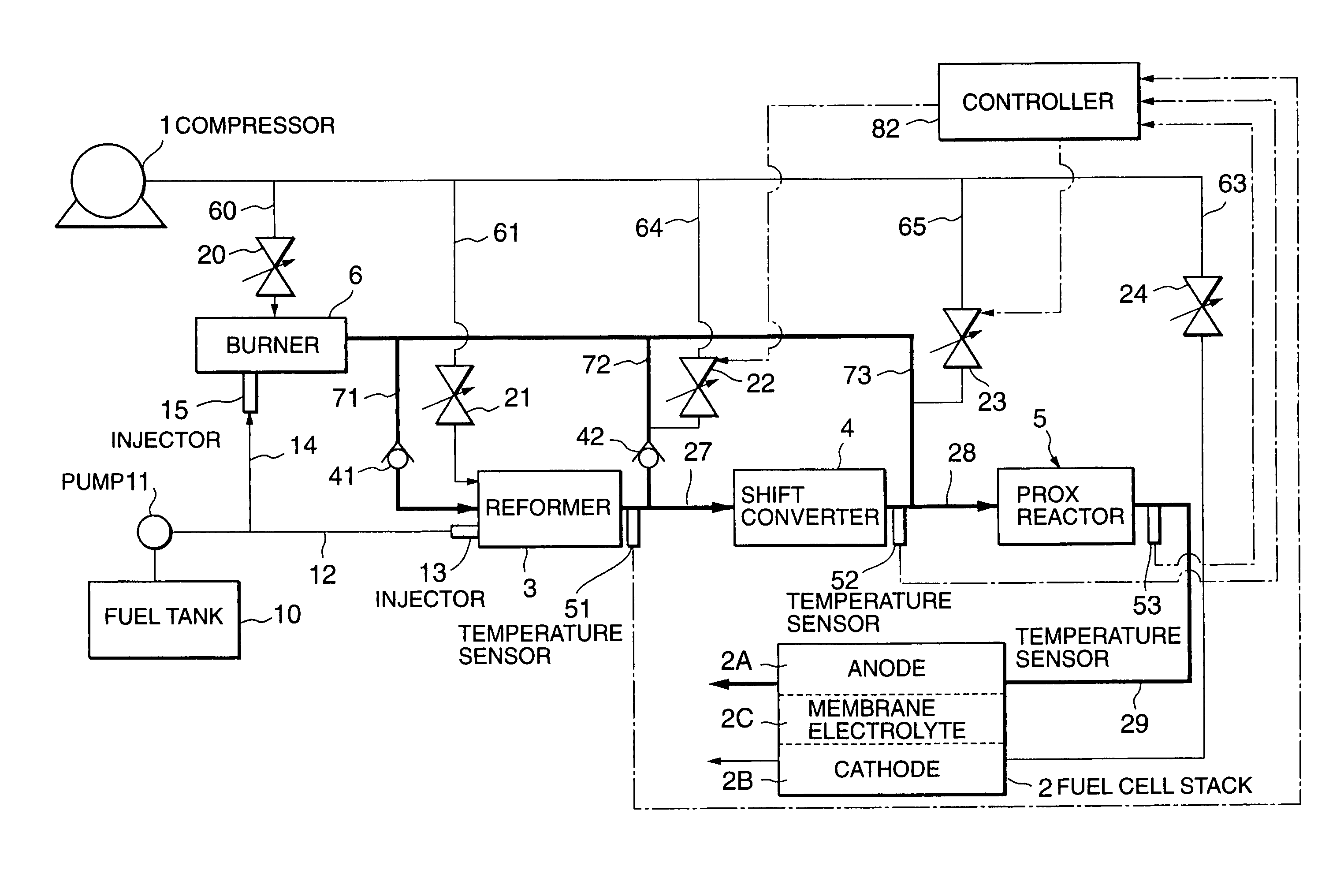
[0089]Referring to FIG. 6, a warm up device according to this embodiment is further provided with air supply passages 64, 65 and air supply valves 22, 23 in addition to the constitution of the warm up device according to the first embodiment in FIG. 1. Moreover, in the first embodiment the temperature sensors 51-53 were described as experiment equipment for obtaining design data, but in this embodiment the temperature sensors 51-53 are provided as constitutional elements of the warm up device. The warm up device of this embodiment is also provided with a controller 82 for controlling the opening of the air supply valves 22 and 23 during start up of the fuel cell power plant. Meanwhile, the gas mixers 31 and 32 provided in the first embodiment have been omitted from this embodiment.

[0090]The air supply passage 64 supplies the combustion gas supply passage 72 with air from the compressor 1 through the air suppl...

first embodiment

[0095]Next, in a step S3, the controller 82 compares the heat amount required for warming up the shift converter 4 with a preset heat amount for warming up the shift converter 4. The preset heat amount for warming up the shift converter 4 corresponds to the required heat amount when the shift converter 4 is warmed up from the set initial temperature described in relation to the first embodiment, or in other words to a set warm up heat amount.

[0096]If the heat amount required for warming up the shift converter 4 is smaller than the set warm up heat amount, the controller 82 opens the air supply valve 22 in a step S4. Following the processing in the step S4, the controller 82 performs the processing of a step S5.

[0097]If, on the other hand, the heat amount required for warming up the shift converter 4 is not smaller than the set warm up heat amount in the step S3, the controller 82 skips the step S4 and performs the processing of the step S5.

[0098]In the step S5, the controller 82 com...

third embodiment

[0116]Next, referring to FIGS. 8 and 9, this invention will be described.

[0117]Referring to FIG. 8, a warm up device according to this embodiment is provided with a flow control valve 80 in the combustion gas supply passage 73 in place of the air supply valves 22 and 23 of the second embodiment.

[0118]In the second embodiment, the flow rate of the combustion gas which is supplied to the catalytic reactors 3-5 was altered by means of air supply from the air supply valves 22 and 23, but in this embodiment the flow rate of the combustion gas which is supplied to the PROX reactor 5 is altered by manipulating the flow control valve 80.

[0119]During the start up period of the reforming system, air is supplied through the air supply passage 64 to the combustion gas supply passage 72 at all times. Similarly, air is supplied through the air supply passage 65 to the combustion gas supply passage 73 at all times. The flow control valve 80 is provided downstream of the point of convergence betwee...


PUM

PropertyMeasurementUnit
operating temperatureaaaaaaaaaa

Abstract

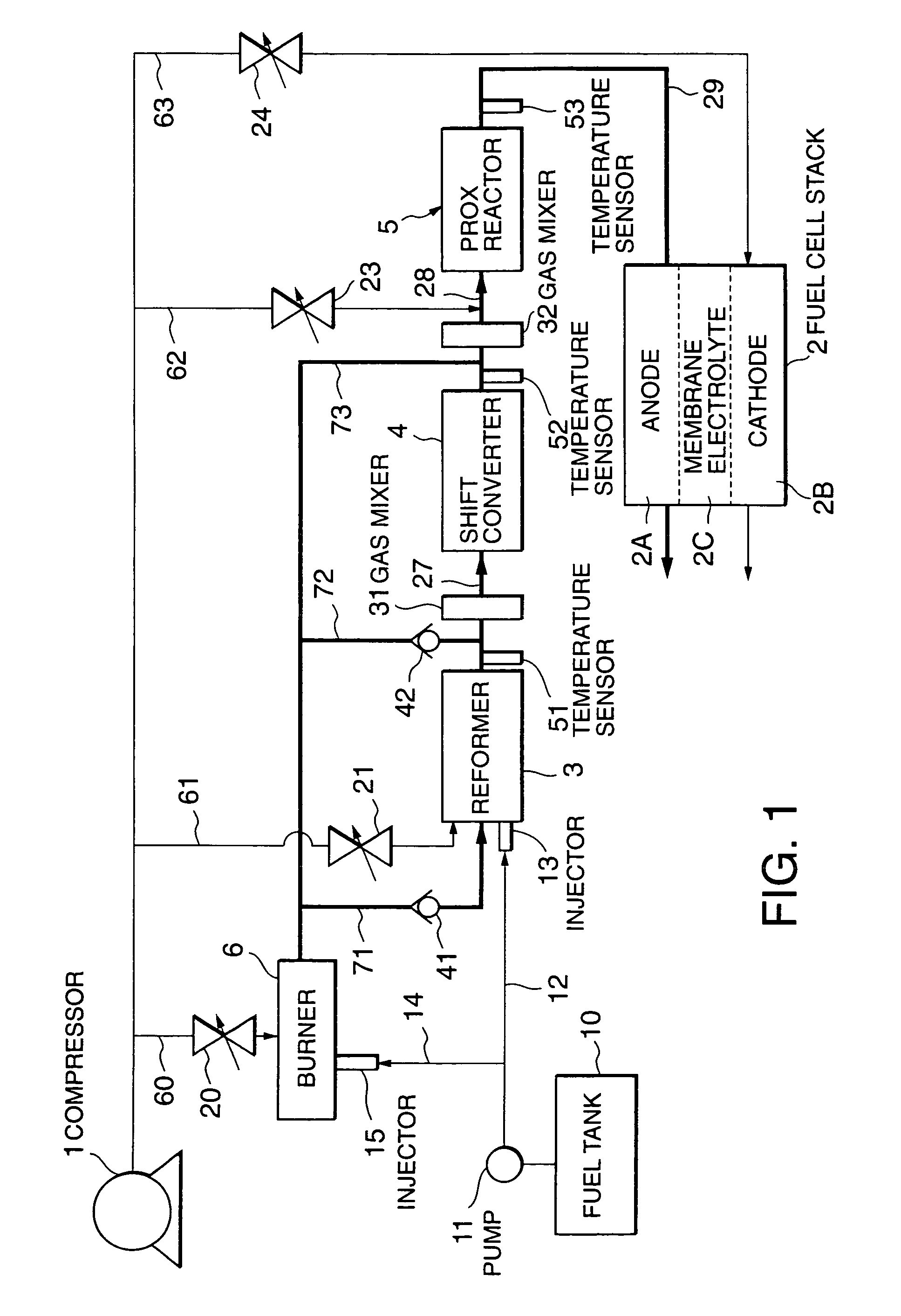
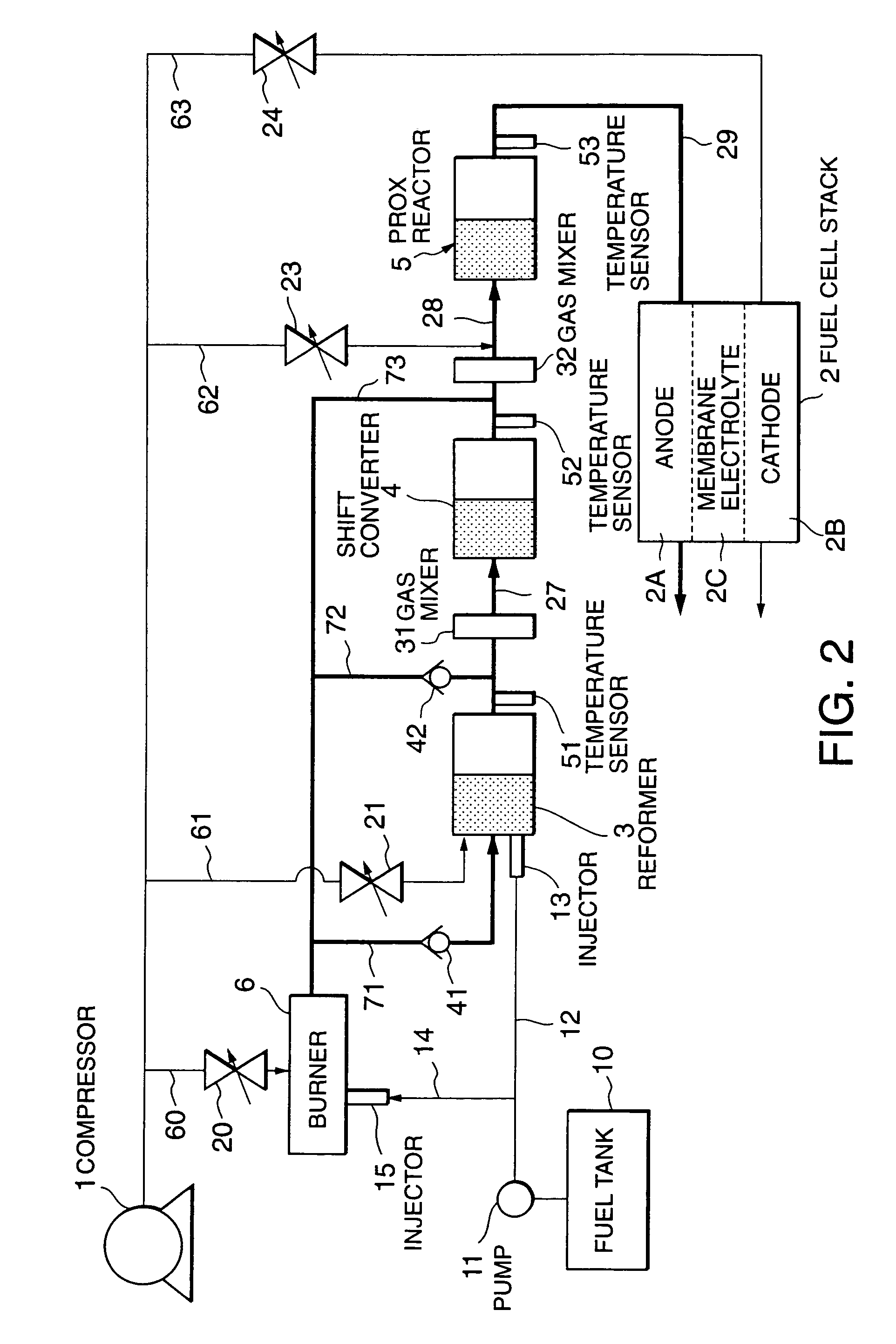
In a fuel cell power plant, carbon monoxide contained in reformate gas which is produced by a reformer (3) by means of a catalytic fuel reaction is removed by the respective catalytic reactions of a shift converter (4) and a preferential oxidation reactor (5). During start up of the fuel cell power plant, a burner (6) burns fuel to produce combustion gas and the combustion gas is supplied individually to the reformer (3), shift converter (4) and preferential oxidation reactor (5) through combustion gas supply passages (71-73) thereby simultaneously completing warming up of these catalytic reactors (3-5).

Description

FIELD OF THE INVENTION[0001]This invention relates to the warming up of a fuel cell power plant using reformate gas.BACKGROUND OF THE INVENTION[0002]In a fuel cell power plant in which the hydrogen required by a fuel cell stack is obtained by fuel reforming, catalysts are used in reactors such as a reformer and a carbon monoxide removal device. It is therefore necessary to warm up each reactor upon start up of the fuel cell power plant so that these catalysts reach activation temperature. In relation thereto, JP05-303970, published by the Japanese Patent Office in 1993, discloses a warm up device for warming up a reformer and carbon monoxide removal device using a single burner.[0003]In this warm up device, fuel combustion is performed by the burner and the reformer is warmed up using the heat generated upon combustion. Combustion gas is then led to the carbon monoxide removal device, whereupon the carbon monoxide removal device is warmed up using the heat of the combustion gas.SUMM...

Claims


Application Information

Patent Timeline
Patent Type & Authority Patents(United States)
IPC IPC(8): F23N5/20H01M8/04C01B3/36B01J19/00C01B3/48H01M8/06
CPCB01J19/0013C01B3/48H01M8/04373H01M8/04776H01M8/0625H01M8/0668B01J2208/00061B01J2208/00504B01J2208/00646B01J2208/00716B01J2219/00006B01J2219/00191C01B2203/0227C01B2203/0233C01B2203/0244C01B2203/0261C01B2203/0283C01B2203/044C01B2203/047C01B2203/066C01B2203/0811C01B2203/0844C01B2203/142C01B2203/1604C01B2203/1619C01B2203/1623C01B2203/169C01B2203/82H01M8/04022H01M8/0618Y02E60/50H01M8/04
Inventor IIO, MASATOSHI
Owner NISSAN MOTOR CO LTD
Learn More