Electron beam tubes

a technology of electron beam and tube body, which is applied in the direction of transit tube circuit elements, transit tube vessels/containers, klystrons, etc., can solve the problems of mechanical stress between the components of the tube, damage to the ceramic walls, and changes in temperature in the device, so as to achieve the effect of reducing stress

Inactive Publication Date: 2009-01-13
E2V TECH (UK) LTD
View PDF8 Cites 0 Cited by
  • Summary
  • Abstract
  • Description
  • Claims
  • Application Information

AI Technical Summary

Benefits of technology

[0008]The invention permits relative radial movement of components of the tube, in order to alleviate stress produced by differential thermal expansion between the components. The invention includes means arranged to produce relative sliding movement in the form of a member interposed between the components. This arrangement maintains the integrity of the vacuum envelope.

Problems solved by technology

A problem that may be encountered with such devices is that changes in temperature in the device can give rise to mechanical stress between components of the tube.
However, it has been found that, in certain conditions, even with the inclusion of balance rings, thermal stresses may be significant and may even cause damage to the ceramic walls defining the vacuum envelope.

Method used


Image

  • Electron beam tubes
  • Electron beam tubes
  • Electron beam tubes

Examples


Embodiment Construction

[0017]Like reference numerals refer to like parts throughout the specification, and may not be described in detail in the different drawing figures.

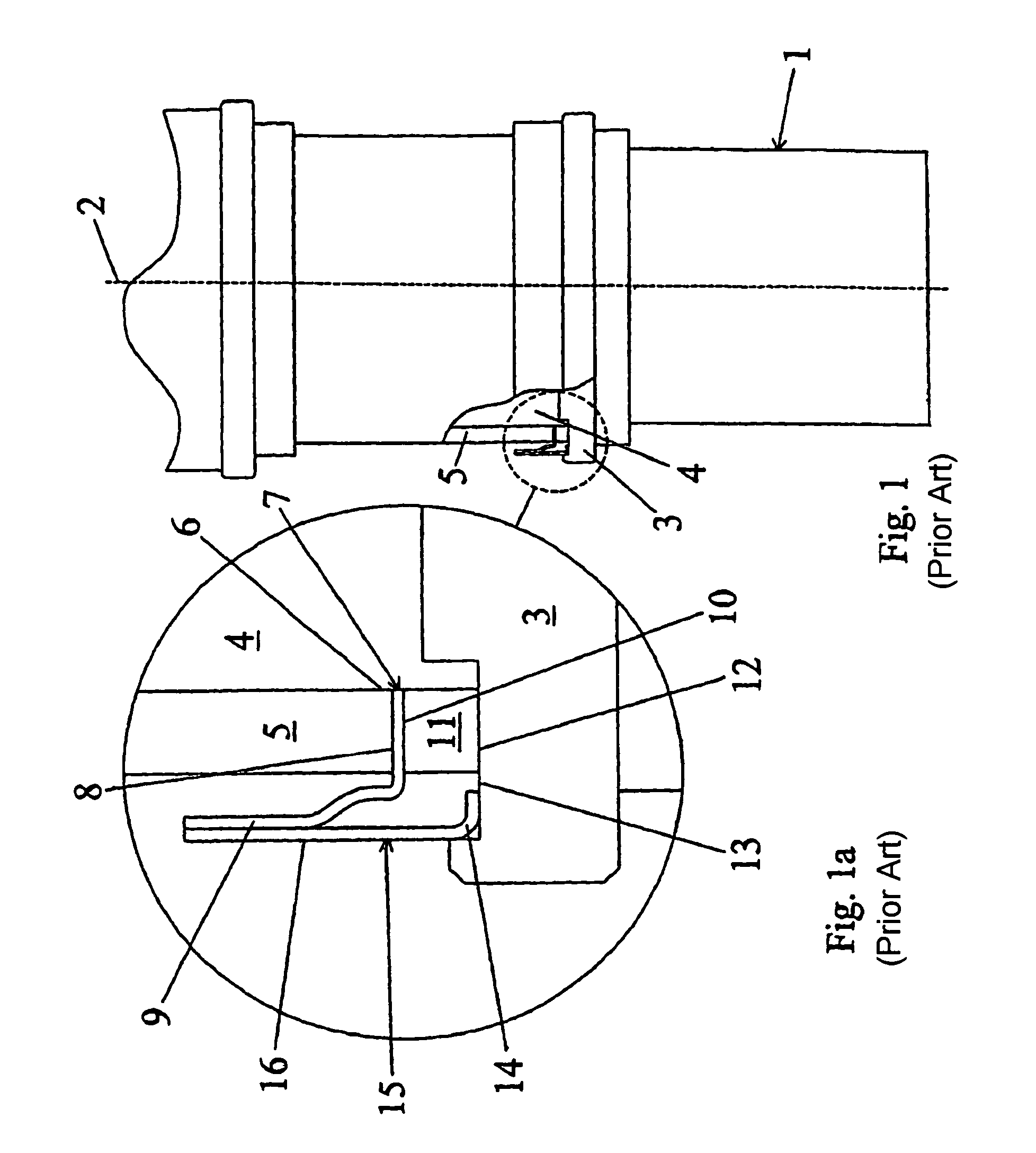
[0018]FIGS. 1 and 1a illustrate part of a conventional electron beam tube, indicated generally in FIG. 1 by reference numeral 1, the tube having a longitudinal axis 2. The part illustrated in these Figures generally comprises the RF interaction region for the tube incorporating a drift tube assembly. Only one side of the tube is shown in detail in FIG. 1a, the components illustrated being approximately symmetrical about the longitudinal axis.

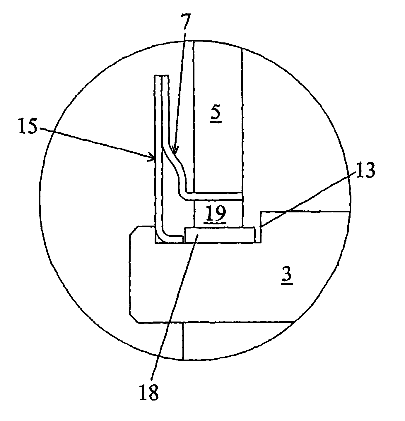
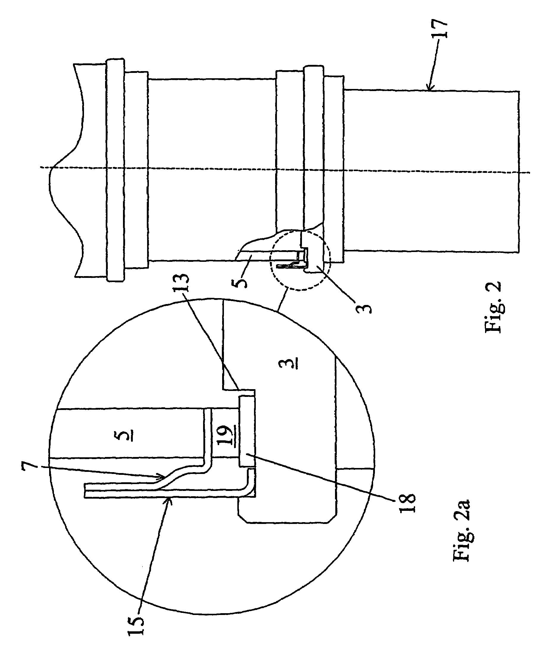
[0019]A mounting plate 3 for the drift tube is shown in FIG. 1a. The mounting plate is typically of copper, stainless steel or nickel. A vacuum envelope 4 for the tube is partially defined by a cylindrical wall of RF transparent material, such as alumina. The cylindrical wall 5 is substantially coaxial with the longitudinal axis 2. The mounting plate 3 also forms part of the vacuum envelope 4. The cy...


PUM


Abstract

An electron beam tube (17) having a longitudinal axis comprises a first component, such as a ceramic wall (5) and a second component such as a drift tube assembly having a mounting plate (3). The tube further comprises means, such as member (18), arranged to allow relative sliding movement of the first component relative to the second component in a radial direction. The invention helps to alleviate mechanical stresses caused by differential thermal expansion of the components.

Description

FIELD OF THE INVENTION[0001]This invention relates to electron beam tubes, and particularly to linear beam devices.BACKGROUND OF THE INVENTION[0002]Linear beam devices are employed in order to amplify signals at high frequencies by modulating an electron beam.[0003]Examples of such devices are klystrons and Inductive Output Tubes (IOTs). Such devices are typically employed as the final stage of amplification in television transmitters at frequencies within the UHF range (470 to 800 MHz). A typical linear beam device comprises an electron gun for generating a beam of electrons, an RF interaction region, for example a series of drift tubes, where amplification of an RF signal takes place and a collector for dissipating the electron beam after it has left the RF interaction region. Amplification of the signal takes place within a vacuum envelope.[0004]Such devices may be of the so-called external cavity type, in which the vacuum envelope comprises a plurality of ceramic cylinders attac...

Claims


Application Information

Patent Timeline
Patent Type & Authority Patents(United States)
IPC IPC(8): H01J23/12H01J5/02H01J5/26H01J23/00H01J23/20
CPCH01J5/02H01J23/12H01J2225/04H01J2225/10
Inventor BARDELL, STEPHENAITKEN, STEVENANDREWS, STUART WILLIAMO'SULLIVAN, NEILWHEELHOUSE, ALAN EDWARD
Owner E2V TECH (UK) LTD
Why Eureka
Try Eureka