Examination system and examination method

a technology of examination system and examination method, which is applied in the direction of speed measurement using gyroscopic effects, surgical microscopes, gyroscopes/turn-sensitive devices, etc., can solve the problems of high concentration and complicated procedure of surgeons, and achieve the effect of simplifying the localization of specific tissue types

Active Publication Date: 2009-01-13
CARL ZEISS SURGICAL +1
View PDF15 Cites 30 Cited by
  • Summary
  • Abstract
  • Description
  • Claims
  • Application Information

AI Technical Summary

Benefits of technology

[0007]It is an object of the present invention to provide a system and a method that may simplify localizing specific tissue types in an image of a microscope.
[0010]The examination system may enable the user to perceive an extension of a specific type of tissue in the tissue region under examination, without having to avert his view from the image of the tissue region generated by the optical system. This is because the viewer may move the measuring head across the tissue region while observing the optical image thereof, and the examination system may provide the marking or indication of the image at those locations of the image where the tissue qualifying system discriminates a certain data category from the data sampled by the measuring head. Since these markings or indications may be provided directly in the image generated by the optical system, the viewer does not have to avert his view from, e.g., a display for generating the optical image of the tissue region, as this was necessary in the conventional system.
[0016]The indication system preferably comprises a display for displaying the marking and a first beam splitter for coupling an image of the displayed marking into a beam path of the microscope, whereby a simultaneous perceptibility of both the optical image generated by the microscope and the marking is made possible.

Problems solved by technology

This procedure is complicated and requires high concentration on the part of the surgeon, because the success of the operation depends on the extent to which the surgeon can memorize the extension of the tumor.

Method used


Image

  • Examination system and examination method
  • Examination system and examination method
  • Examination system and examination method

Examples


Embodiment Construction

[0029]In the embodiments described below, components which are identical in function and structure are designated as far as possible by the same reference numerals. Therefore, to understand the features of the individual components of a specific embodiment, the descriptions of other embodiments should be referred to.

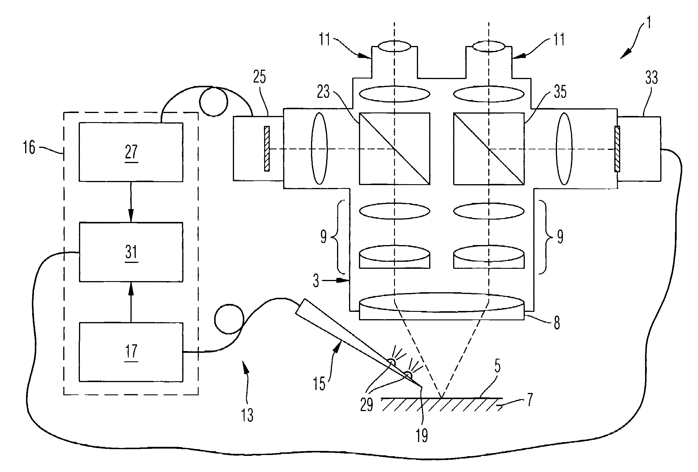
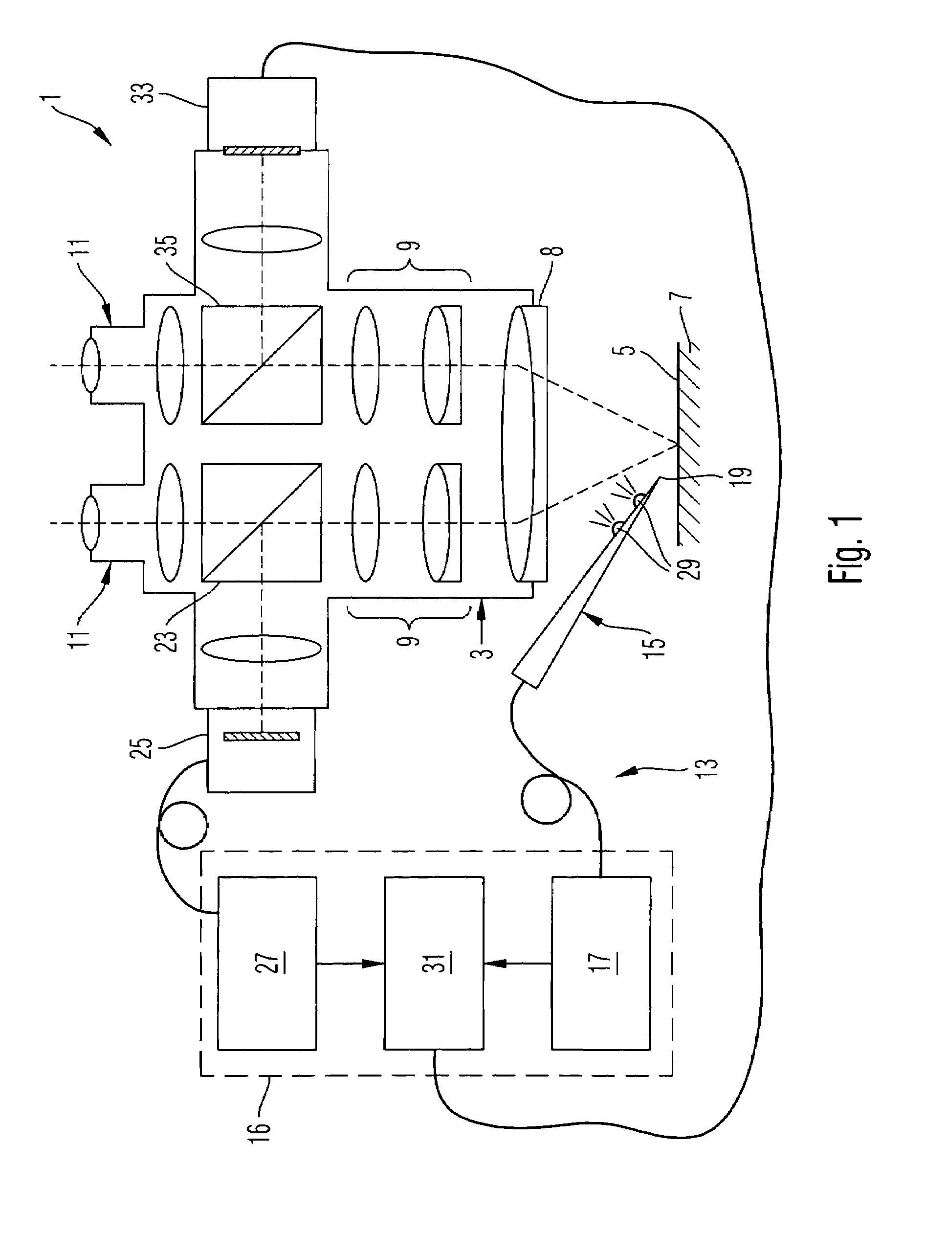
[0030]An exemplary examination system 1 shown in FIG. 1 comprises a surgical microscope 3 for generating a stereo-microscopic image of a tissue area 7 arranged in an object plane 5. To this end, the operation microscope 3 comprises an objective lens 8 and a beam path with two zoom systems 9 for imaging the image of the object plane 5 via two ocular lenses 11 to both the left and right eyes of the viewer.

[0031]Furthermore, the examination system 1 comprises a tissue qualifying system 13, having an ultrasound measuring head 15 for sampling tissue data and a discriminating device 17 for evaluating the tissue data. The discriminating device 17 may be realized as a software c...


PUM


Abstract

An examination system and a corresponding examination method, comprise: Arranging a tissue region in a vicinity of an object plane of a microscope and generating an optical image of the tissue region, receiving tissue data from a measuring head separate from the microscope, discriminating the tissue data into at least two data categories and displaying markings in the optical image of the tissue region in dependence of the discriminated data category and a relative position between a component of the microscope and the measuring head.

Description

[0001]This application claims the benefit of priority application DE102 52 837.3 filed in Germany on Nov. 13, 2002, the subject matter of which is incorporated herein by reference.BACKGROUND OF THE INVENTION[0002]1. Field of the Invention[0003]The present invention relates to an examination system and an examination method for displaying a tissue region to a user. The tissue region is in particular a portion of a patient to undergo a surgical operation, and the user is in particular a surgeon performing such surgical operation.[0004]2. Brief Description of Related Art[0005]In a conventional surgical system and method, e.g., a near-surface tumor is to be excised from the tissue region, and the surgical operation is performed by a surgeon viewing the tissue region through a surgical microscope. An ultrasound system may be used for localizing the tumor to be excised. The surgeon scans the tissue region in which the tumor is presumed with a measuring head of the ultrasound system, and t...

Claims


Application Information

Patent Timeline
Patent Type & Authority Patents(United States)
IPC IPC(8): G06K9/00G01C9/00G02B21/32A61B10/00A61B17/00A61B19/00G02B21/36
CPCA61B19/5244A61B19/50A61B19/5212A61B19/5223A61B2017/00106A61B2017/00221A61B2019/262A61B2019/5255A61B2019/5265A61B2019/5276A61B2019/5291A61B2019/5445A61B34/10A61B34/20A61B90/20A61B90/361A61B2034/2055A61B2034/2065A61B2090/365A61B2090/378A61B2090/3945A61B2090/502Y10S128/922
Inventor HAISCH, MICHAEL
Owner CARL ZEISS SURGICAL
Why Eureka
Try Eureka