Method of detecting error location, and error detection circuit, error correction circuit, and reproducing apparatus using the method

a technology of error location and error correction circuit, applied in the field of signal processing technology, can solve the problems of second burst error, inability to detect burst errors, burst errors, etc., and achieve the effect of improving the capability of error correction, and improving the capability of detecting error locations

Inactive Publication Date: 2009-01-13
SANYO ELECTRIC CO LTD
View PDF7 Cites 19 Cited by
  • Summary
  • Abstract
  • Description
  • Claims
  • Application Information

AI Technical Summary

Benefits of technology

[0014]According to this aspect, an error location is estimated based on the detection code, and an error location is also estimated based on the characteristic of the bit string adjoining the detection code. It is therefore possible to estimate the error location that cannot be detected by the detection code alone. This improves the capability of detecting error locations.
[0017]Still another aspect of the present invention is a circuit which corrects an error included in a data signal. This circuit comprises: a reading unit which reads a data signal; a first estimation unit which estimates an error location based on a detection code for estimating an error location included in the read data signal; a second estimation unit which estimates an error location based on a characteristic of a bit string adjoining the detection code included in the read data signal; and a correction unit which corrects the error locations estimated by the first estimation unit and the second estimation unit. This improves the capability of detecting error locations, and improves the capability of error correction.
[0018]Still another aspect of the present invention is a reproducing apparatus. This apparatus comprises: a reading unit which reads a data signal recorded on a recording medium; a first estimation unit which estimates an error location based on a detection code for estimating an error location included in the read data signal; a second estimation unit which estimates an error location based on a characteristic of a bit string adjoining the detection code; a correction unit which corrects the error locations estimated by the first estimation unit and the second estimation unit; and a reproduction unit which performs reproduction based on the corrected data signal. This improves the capability of detecting error locations and improves the capability of error correction, thereby allowing high quality reproduction.

Problems solved by technology

Burst errors occur from such factors as disk flaws and adhesion of dust particles to the disk surface.
In this way, there can often occur such cases that second burst errors 36b cannot be detected.

Method used


Image

  • Method of detecting error location, and error detection circuit, error correction circuit, and reproducing apparatus using the method
  • Method of detecting error location, and error detection circuit, error correction circuit, and reproducing apparatus using the method
  • Method of detecting error location, and error detection circuit, error correction circuit, and reproducing apparatus using the method

Examples


first embodiment

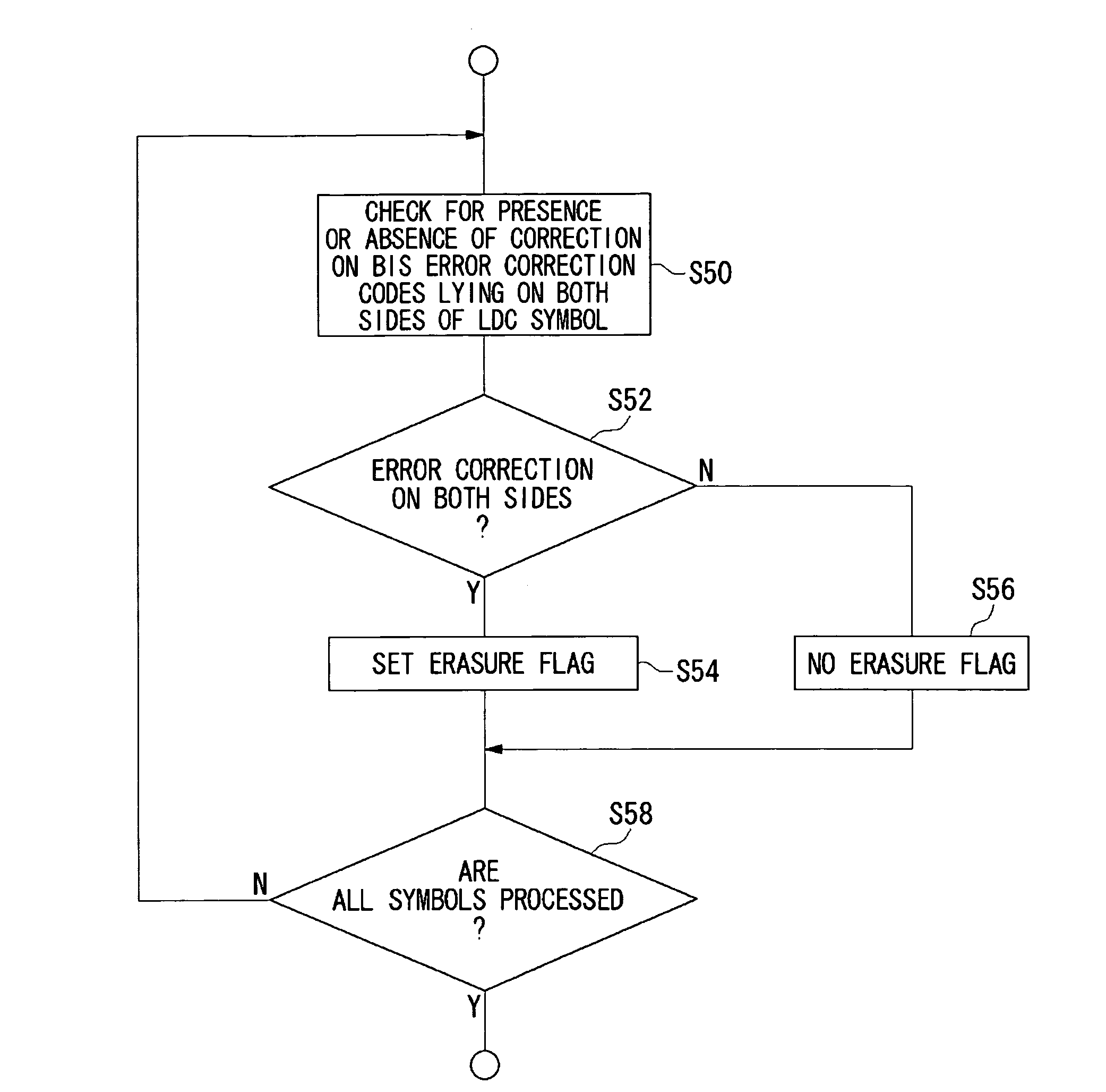
[0030]A first embodiment will deal with a method of detecting an error location included in a data signal and a circuit for correcting an error location by using the detection method.

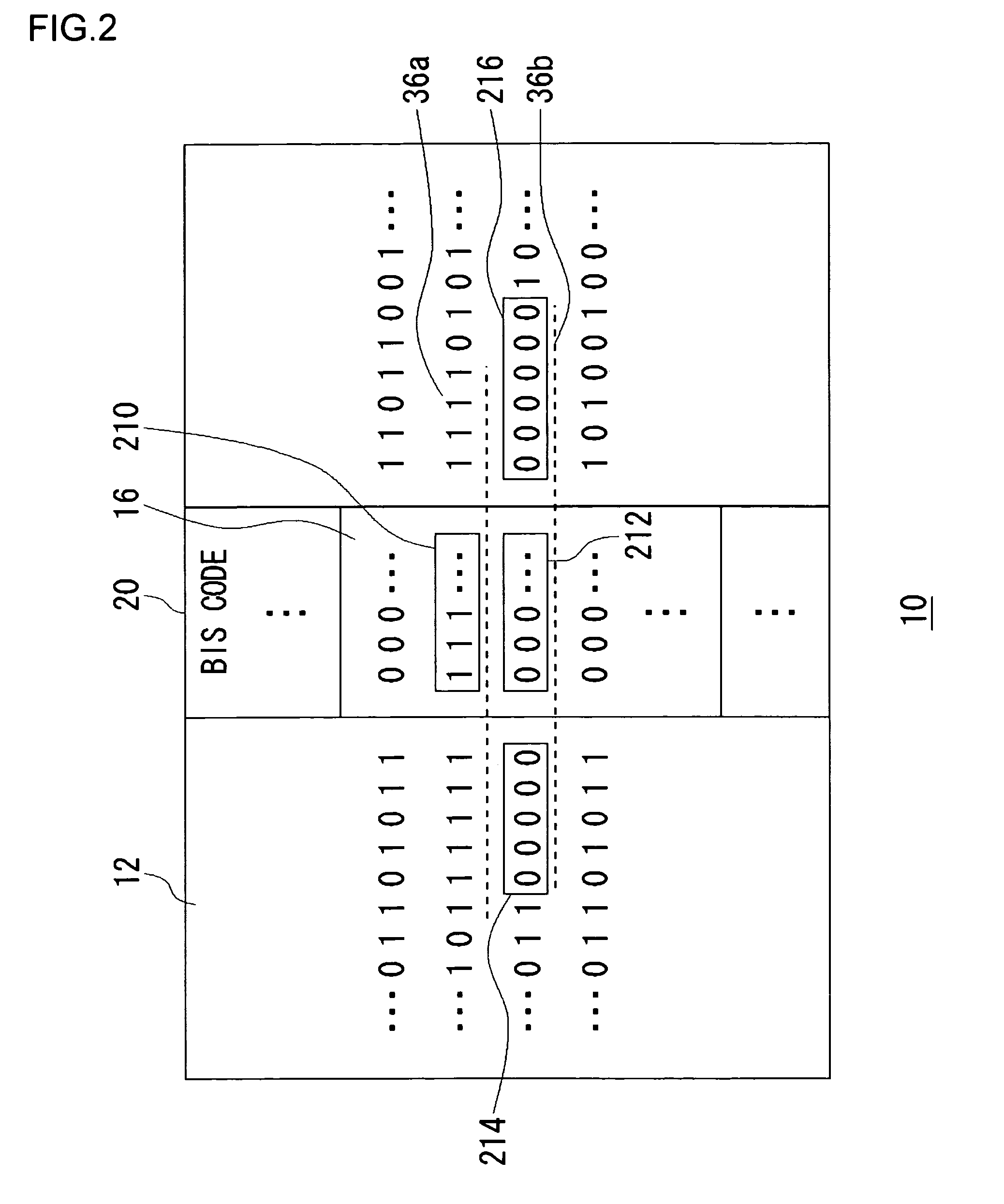
[0031]FIG. 2 is a diagram for explaining the method of detecting an error location according to the first embodiment. This diagram shows part of a code block 10. The code block 10 contains user data 12 and BIS code 20. In general, when there is no error, all the bit values of reserve information 16 in the BIS code 20 are “0”. When a burst error occurs and bit values “1” appear consecutively as in a first burst error 36a, the reserve information 16 which is supposed to have bit values “0” exhibits bit values “1” as in the first reserve information 210. The first reserve information 210 is detected as an error location during correction processing on the BIS code 20. On the other hand, if bit values “0” appear consecutively as in a second burst error 36b, the error location will not be detected during the...

second embodiment

[0042]A second embodiment will deal with an apparatus having the function of applying correction processing to a data signal read from an optical disk by using the method of detecting an error location described in the first embodiment.

[0043]FIG. 6 is a block diagram showing a recording and reproducing apparatus 100 according to the second embodiment. The recording and reproducing apparatus 100 has a recording processing section 136 and a reproduction processing section 138. Initially, description will be given of the recording processing section 136. A user data reception unit 102 is an interface for receiving data, for example, from a host computer, an MPEG image encoder, or the like. An LDC correction code generation unit 104 generates parities from the data received at the user data reception unit 102, thereby generating LDC error correction code. An ID generation unit 106 generates addresses corresponding to recording locations of the user data on an optical disk 50, i.e., ID i...


PUM

PropertyMeasurementUnit
lengthsaaaaaaaaaa
lengthsaaaaaaaaaa
recording densitiesaaaaaaaaaa

Abstract

An error correction circuit capable of detecting burst errors included in a data signal with reliability. The error correction circuit comprises a reading unit, a first estimation unit, a second estimation unit, and a correction unit. The reading unit reads the data signal. The first estimation unit estimates error locations based on BIS code included in the data signal, and stores the locations into an error location storing unit. The second estimation unit estimates error locations based on characteristics of bit strings adjoining the BIS code, and stores the locations into the error location storing unit. The correction unit identifies erasure locations based on the error locations stored in the error location storing unit, and performs erasure correction on the erasure locations identified. Since the error locations are estimated based on the BIS code and the characteristics of the bit strings adjoining the BIS code as well, it is possible to detect burst errors without fail.

Description

BACKGROUND OF THE INVENTION[0001]1. Field of the Invention[0002]The invention relates to a signal processing technology. In particular, the invention relates to a method of detecting an error included in a data signal, an error detection circuit using the method, an error correction circuit using the method, and a reproducing apparatus using the method.[0003]2. Description of the Related Art[0004]High-capacity optical disk devices using red laser, such as a digital versatile disk (DVD), have been already put to practical use. Recently, next-generation optical disks which use blue laser sources of near 650 nm in wavelength are under intensive development for the sake of further enhanced recording capacities. Maximizing the recording capacities requires that higher error correction capabilities be provided aside from improved linear recording densities and narrower tracks resulting from a reduction in the wavelength of the recording light sources.[0005]For example, DVD disks have mini...

Claims


Application Information

Patent Timeline
Patent Type & Authority Patents(United States)
IPC IPC(8): H03M13/00G06F11/00G06F11/30G08C25/00G11B20/18G11C29/00H03M13/03H03M13/37H04L1/00
CPCG11B20/18H04L1/0071H04L1/0061H04L1/0045G11B2020/1272
Inventor OKAMOTO, MIYUKIKANAI, SATOSHIFUMA, MASATO
Owner SANYO ELECTRIC CO LTD
Why Eureka
Try Eureka