
Quick adjust ratcheting wrench with cam actuated clamping

a ratcheting wrench and cam-actuated technology, applied in the field of hand-held wrenches, can solve the problems of reducing the durability of the tool, and reducing the effectiveness of the tool, so as to improve the control and efficient transfer of load, reduce wear, and improve durability and reliability

Inactive Publication Date: 2009-01-20
WHEELER THOMAS J
View PDF8 Cites 68 Cited by
  • Summary
  • Abstract
  • Description
  • Claims
  • Application Information

AI Technical Summary

Benefits of technology

[0004]Accordingly, it is an object of the present invention to provide a new type of wrench having features to simplify the structure and construction, advance its convenience of use, durability and effectiveness and reduce its manufacturing cost and weight.
[0007]It will be appreciated that the present invention provides for cam surfaces satisfies an object of the invention in that the cantilever torque present in prior art designs is significantly reduced permitting light weight material construction, reduced wear and improved durability and reliability. The present invention transfers torque directly from the control disc to the cam followers of the jaws. Because the cam follower is positioned in direct line with the V-shaped grip surface of the jaw there is no cantilevered torque applied to the element. The work piece is thusly in a direct line relative to the handle, pawl, control disc and jaws further improving control and efficient transfer of load to the work piece as there is no vertical force vector as present in the prior art. Another object of the invention further reducing manufacturing cost is the absence of a ratcheting mechanism fixing the control and adjusting discs during a return stroke. Yet further, there is a significant load reduction on the adjusting disc. It will be further appreciated that many other additional benefits are provided by the invention.

Problems solved by technology

Further, the structure necessitates the application of similar torque levels transferred to the adjustment disc in both rotation directions for the corresponding cam surfaces to push the jaw elements in the corresponding direction thereby making certain application of the tool ineffective.
Additionally, because the jaw elements are disposed perpendicularly from the control and adjustment discs, the transference of force through to the grip surface creates a cantilevering of the jaw elements generating additional frictional forces impeding operation, increasing wear of the wrench components and reduces the durability of the tool.
The cantilevering further eventually widens the cam grooves which consequently affects the matching of the grip surfaces of the jaw elements with the work piece yet further impeding the operation by increasing the opportunities for the tool to bind.
Of particular noteworthiness is the load transfer through the control disc wherein application of torque to the handle causes a high level of cantilever load on both the control and adjustment discs therefore necessitating hard or harden materials for their construction thereby increasing weight and manufacturing costs over lighter materials.
Finally, a separate ratcheting means is often included between the control and adjustment discs to prevent their relative rotation so as to retain the jaw elements in position during the free return stroke of the wrench handle thereby necessitating significant complications to the tool design.

Method used


Image

  • Quick adjust ratcheting wrench with cam actuated clamping
  • Quick adjust ratcheting wrench with cam actuated clamping
  • Quick adjust ratcheting wrench with cam actuated clamping

Examples


Embodiment Construction

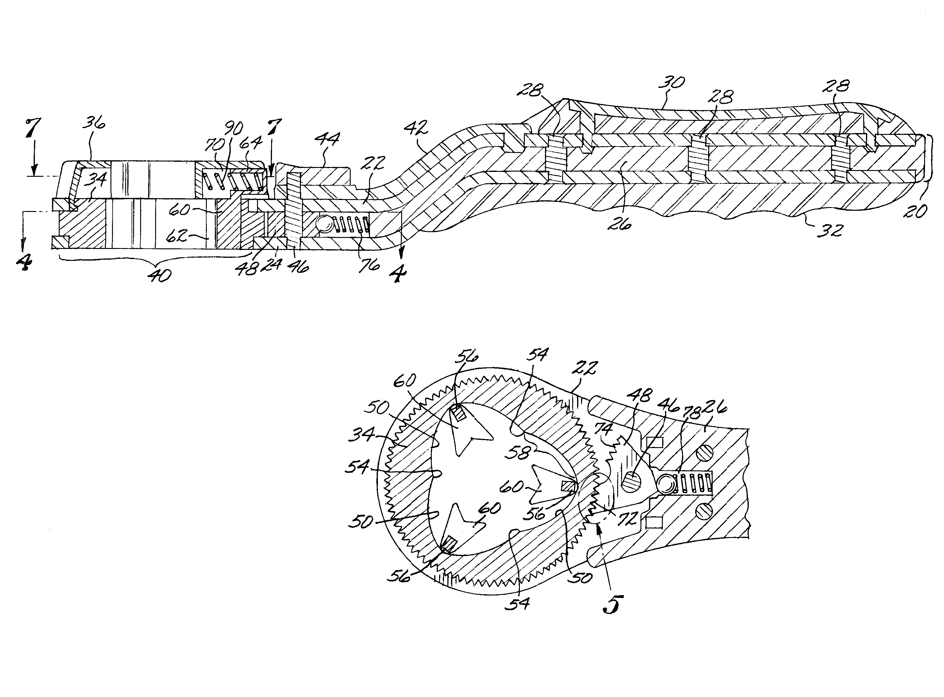
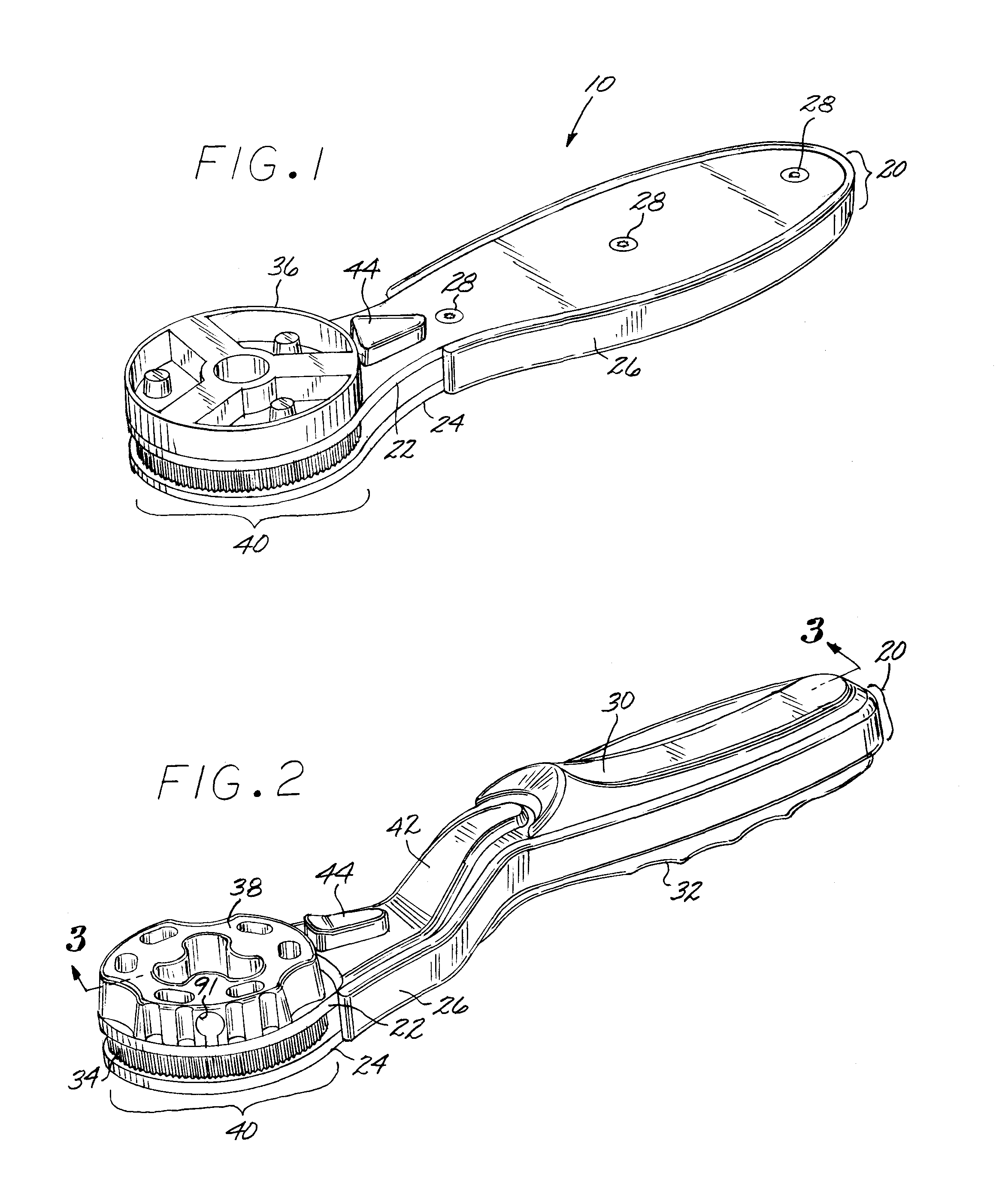
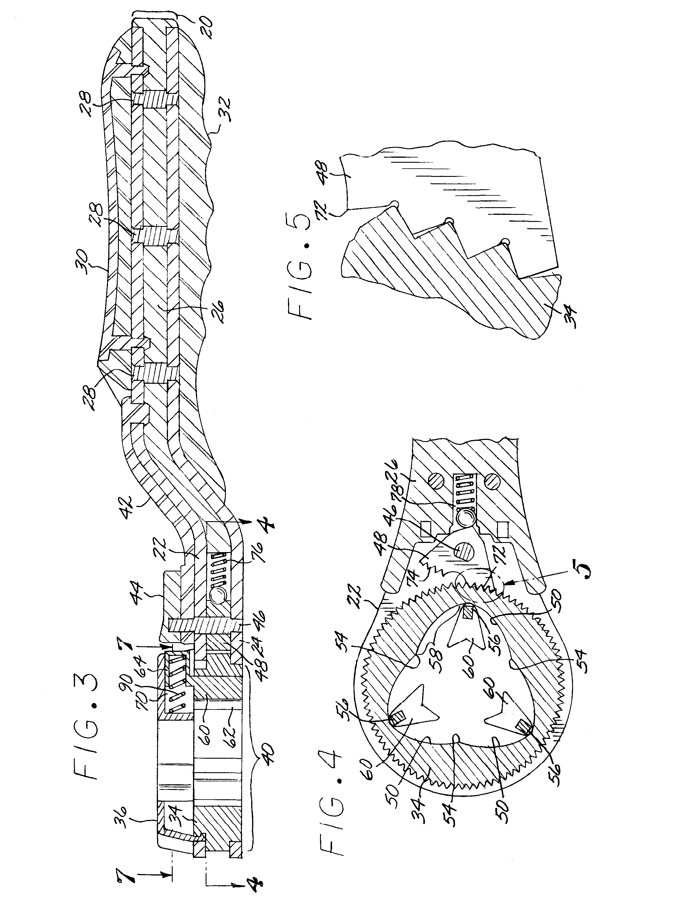
[0024]Although particular embodiments of the invention have been described in detail for purposes of illustration, various modifications may be made without departing from the spirit and scope of the invention. Accordingly, the invention is not to be limited except as by the appended claims. Referring now in greater detail to the various figures of the drawings wherein like reference characters refer to like parts, there is shown in a perspective view at 10 in FIG. 1, a new type of quick adjust ratcheting wrench with cam actuated clamping.

[0025]For clarity, FIG. 1 illustrates a perspective view of the essential adjustable wrench 10 according to the present invention comprising a handle 20 having top and bottom frame elements, respectively at 22 and 24, being preferably constructed of stamped sheet metal each having an annular periphery opening at one end forming the handle housing 40 and being disposed parallel to each other by means of handle insert 26 to which they are fastened wi...


PUM


Abstract

The invention is a wrench with jaws adjusted by a cam mechanism and a ratchet mechanism providing a free return stroke of the handle, a simplified construction, convenience of use, durability, effectiveness, and cost and weight reduction; comprising a handle with housing, annular control and adjusting discs, a plurality of radial guide slots in the adjusting disc and cam features in the control disc, a plurality of jaws in the housing, each jaw, having a slider spring loaded, is positioned in said guide slots, and a cam follower interacting with cam features formed on the inner edge of the control disc; radial guide slots on the surface of the adjusting disc facing the control disc, each guide slot limited by the inner arch-shaped edge of the adjusting disc and open on its periphery; cam followers and profiles provide wedging to the rotation of the discs during the return stroke.

Description

FIELD OF THE INVENTION[0001]The present invention relates to the field of hand wrench tools. More particularly, this invention is directed to a wrench tool with jaws adjusted by a cam mechanism, and a ratchet mechanism for providing a free return stroke of the handle.BACKGROUND OF THE INVENTION[0002]Various types of wrenches having adjustable jaws to grip a range of sizes or diameters of bolts, nuts or other fasteners have been provided with varying degrees of acceptance. Examples of adjustable jaw wrenches include open jaw types wherein the fastener is typically approached from a side and the jaws are then manually adjusted for size to fit a work piece. Ratchet action adjustable jaw wrenches typically approach the fastener from the top and then the jaws are adjusted for size to snuggly fit the fastener. The mechanisms vary in the prior art for tightening the jaws up against a work piece fastener. Adjustable jaw ratchet action wrenches typically have an annularly mounted mechanism w...

Claims


Application Information

Patent Timeline
Patent Type & Authority Patents(United States)
IPC IPC(8): B25B13/46B25B13/18
CPCB25B13/10B25B13/18B25B13/44B25B13/463
Inventor WHEELER, THOMAS J
Owner WHEELER THOMAS J
Learn More