Resin composite fuel hose

a composite fuel and hose technology, applied in the direction of synthetic resin layered products, other domestic articles, mechanical instruments, etc., can solve the problems of high pressure, insufficient sealing properties, and hard resin layer as barrier layer, so as to reduce tightening force and reduce sealing pressure , the effect of easy fitting

Active Publication Date: 2009-01-20
SUMITOMO RIKO CO LTD
View PDF10 Cites 16 Cited by
  • Summary
  • Abstract
  • Description
  • Claims
  • Application Information

AI Technical Summary

Benefits of technology

[0048]According to the present invention, when the outer rubber layer is tightened by the hose claim in a diametrically contracting direction for connecting the fuel hose to the mating pipe, the tightening force can be favorably transmitted to the inner rubber layer, thereby the fuel hose can be connected to the mating pipe under a good or sufficient tightening force.
[0050]Further, the fuel hose can be easily fitted on the mating pipe with a small force.
[0051]And, since the permanent elongation of the inner rubber layer is set equal to or less than 90%, it is prevented over a long period of time that the tightening force is decreased due to fatigue of the inner rubber layer and thereby the sealing pressure is lowered and the fuel permeation resistance is impaired.
[0054]When the rubber hardness degree of the inner rubber layer exceeds 80, the inner rubber layer is too hard to favorably transmit the clamping force by the hose clamp to the mating pipe or the inner rubber layer and to be deformed so as to follow a shape of the mating pipe, whereby the sealing becomes insufficient, and a considerable force is required for fitting of the hose to the mating pipe resulting in less easiness of fitting of the hose.

Problems solved by technology

However, the resin layer as the barrier layer is hard since resin is a material harder than rubber.
So, in a hose including the resin layer laminated on an inner side of the outer rubber layer to an extreme end thereof (an axial end of the hose), when the hose is fitted on a mating pipe, a sealing property becomes insufficient due to poor bonding between the mating pipe and the resin layer that defines an inner surface of the hose.
And, since the resin layer defining the inner surface of the hose is hard and has a large deformation resistance, a great force is required for fitting or slipping the hose on the mating pipe.
This causes a problem that easiness of connection of the hose and the mating pipe is impaired.
However, in case of the hose 200 shown in FIG. 5, such production method cannot be employed.
And, the clamping force is not transmitted favorably or suitably to the inner rubber layer, the inner rubber layer does not exert the clamping force sufficiently to the mating pipe, resulting in leakage of a transported fluid.
And, even supposing that the hose is tightened to the mating pipe with sufficient tightening force initially, the inner rubber layer fatigues and is subject to stress relaxation due to aging.
At that time, since the tightening force by the hose clamp is hard to be exerted to the inner rubber layer, a sealing pressure of the hose to the mating pipe is not applied sufficiently, resulting in leakage of the transported fluid.
Further, due to lack of the tightening force in an early period or after a certain period of time, resulting also in lowered fuel permeation resistance.
Namely, inherent in this type is a problem that easiness of fitting of the hose, namely easiness of connection of the hose is not so good.

Method used


Image

  • Resin composite fuel hose
  • Resin composite fuel hose
  • Resin composite fuel hose

Examples


Embodiment Construction

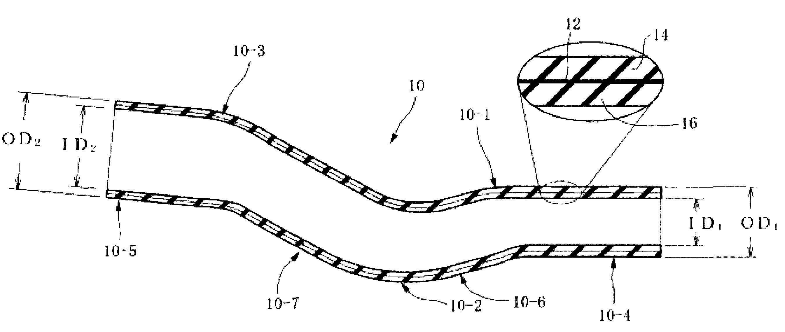
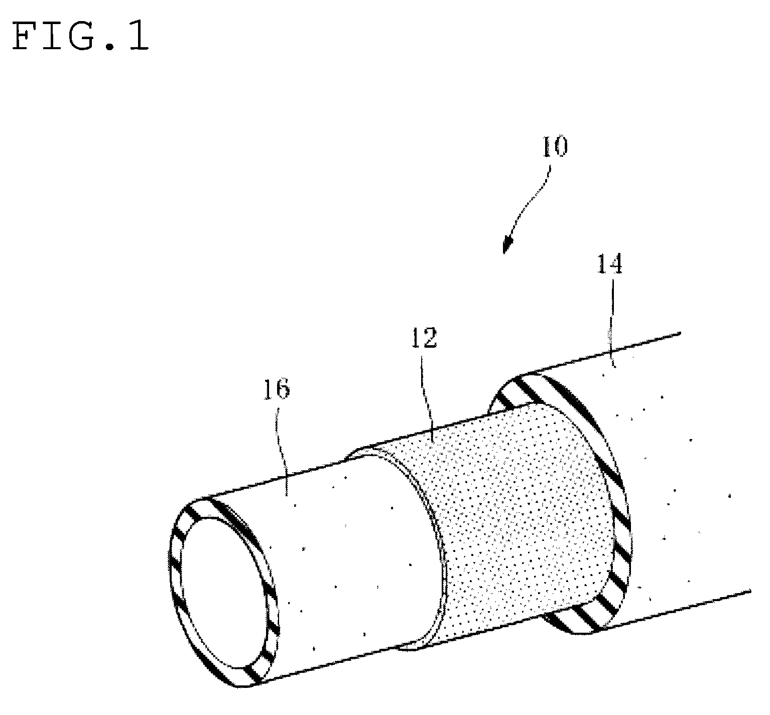
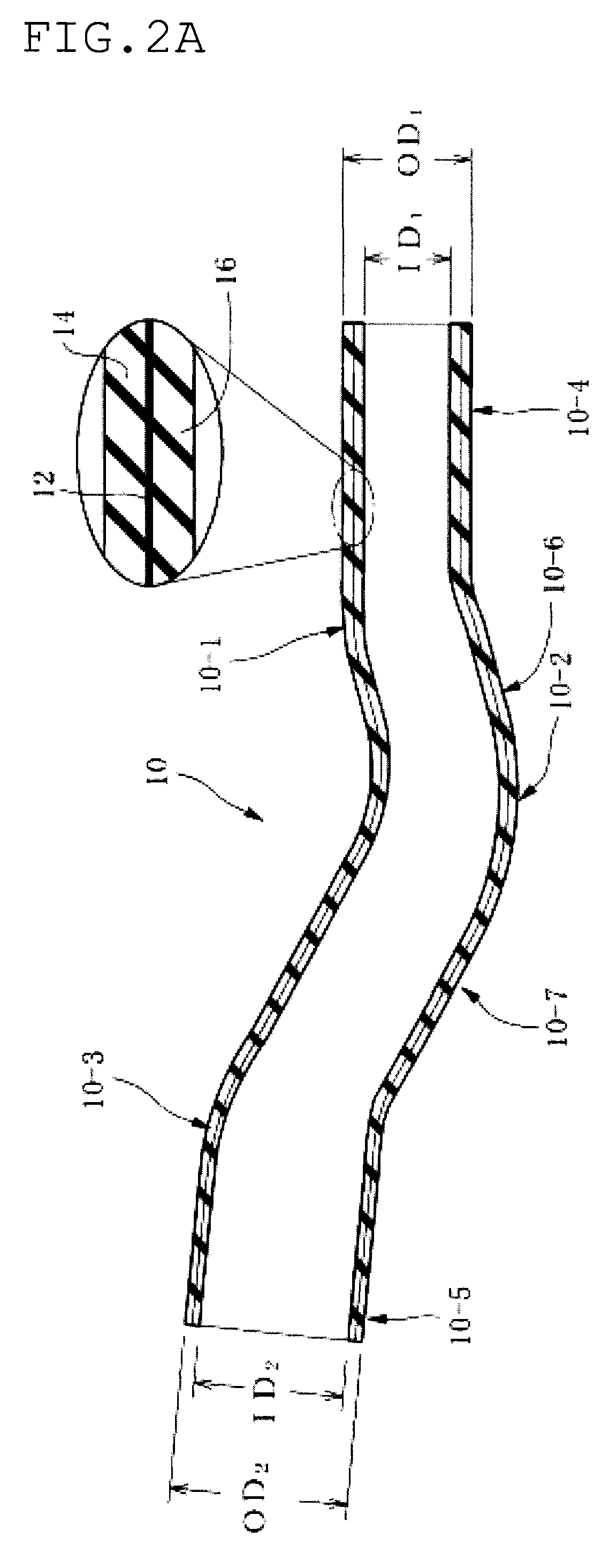
[0068]In FIGS. 1 and 2, reference numeral 10 indicates a fuel hose or fuel transporting hose (filler hose, hereinafter simply referred to as a hose) for transporting a fuel injected in a fuel inlet to a fuel tank in a motor vehicle. The hose 10 has multilayer construction comprising a resin layer 12 as a barrier layer having a permeation resistance to a transported fluid, an outer rubber layer 14 on an outer side of the resin layer 12, and an inner rubber layer 16 as an inner surface layer on an inner side of the resin layer 12.

[0069]Here, the resin layer 12 in the middle of the layers is formed to extend from one axial end to the other axial end of the hose, or to extend from one axial edge portion to the other axial edge portion thereof.

[0070]The hose 10 entirely has a curved or bent shape.

[0071]Specifically, the hose 10 has curved portions 10-1, 10-2 and 10-3 at predetermined axial positions of the hose 10. And, the hose 10 has straight portions or straight tubular portions (port...


PUM

PropertyMeasurementUnit
elongationaaaaaaaaaa
permanent elongation rateaaaaaaaaaa
elongationaaaaaaaaaa

Abstract

A resin composite fuel hose of a multilayer construction includes a resin layer as a barrier layer having a fuel permeation resistance, an inner rubber layer as an inner surface layer laminated on an inner side of the resin layer and an outer rubber layer laminated on an outer side of the resin layer. The outer rubber layer has a rubber hardness degree equal to or greater than that of the inner rubber layer, and the inner rubber layer has a permanent elongation equal to or less than 90%.

Description

BACKGROUND OF THE INVENTION[0001]1. Field of the Invention[0002]The present invention relates to a resin composite fuel hose including a resin layer that is disposed in the middle of multilayer, has a permeation resistance to a fuel and serves as a barrier layer.[0003]2. Description of the Related Art[0004]For application of a fuel hose (fuel filler hose) transporting a fuel injected in a fuel inlet to a fuel tank in a motor vehicle, a typical rubber hose made of a blend of acrylonitrile-butadiene rubber and polyvinyl chloride (NBR / PVC blend, NBR+PVC) or the like has been conventionally used. Such rubber hose has a high vibration-absorbability, easiness of assembly, and an excellent permeation resistance to a fuel (gasoline).[0005]However, recently, in view of global environmental conservation, regulations on restriction of permeation of motor vehicle fuel has been tightened, and demand for fuel permeation resistance is expected to increase more and more in future.[0006]As a counter...

Claims


Application Information

Patent Timeline
Patent Type & Authority Patents(United States)
IPC IPC(8): F16L11/00B32B7/022
CPCB32B1/08F16L11/045F16L11/081F16L11/12B32B7/02B32B25/042B32B25/14B32B27/304B32B27/322B32B25/08Y10T428/1393F16L2011/047B32B2270/00B32B2307/7265B32B2597/00B32B7/022
Inventor SAKAZAKI, KAZUSHIGEMORI, HIROYOSHIIIO, SHINJI
Owner SUMITOMO RIKO CO LTD
Why Eureka
Try Eureka