Spray coating device for spraying coating material, in particular coating powder

Active Publication Date: 2009-01-20
GEMA SWITZERLAND GMBH
View PDF24 Cites 1 Cited by
  • Summary
  • Abstract
  • Description
  • Claims
  • Application Information

AI Technical Summary

Benefits of technology

[0005]The objective of the present invention is to attain equal or better efficiency in controlling the coating material spray flow and the quantity of coating material required for such coating while using less shaping air per unit time.

Problems solved by technology

However it also applies to spray apparatus which are not designed to electrostatically charge coating materials.
Spray apparatus fitted with shaping-air outlets of annular gap geometry incur the drawback that if said gap is supported along its longitudinal direction at several places, manufacturing constraints will preclude uniform gap size.
Such a drawback however is averted by using boreholes instead of an angular gap, especially if the body containing said boreholes remains undivided at the borehole site.

Method used


Image

  • Spray coating device for spraying coating material, in particular coating powder
  • Spray coating device for spraying coating material, in particular coating powder
  • Spray coating device for spraying coating material, in particular coating powder

Examples


Embodiment Construction

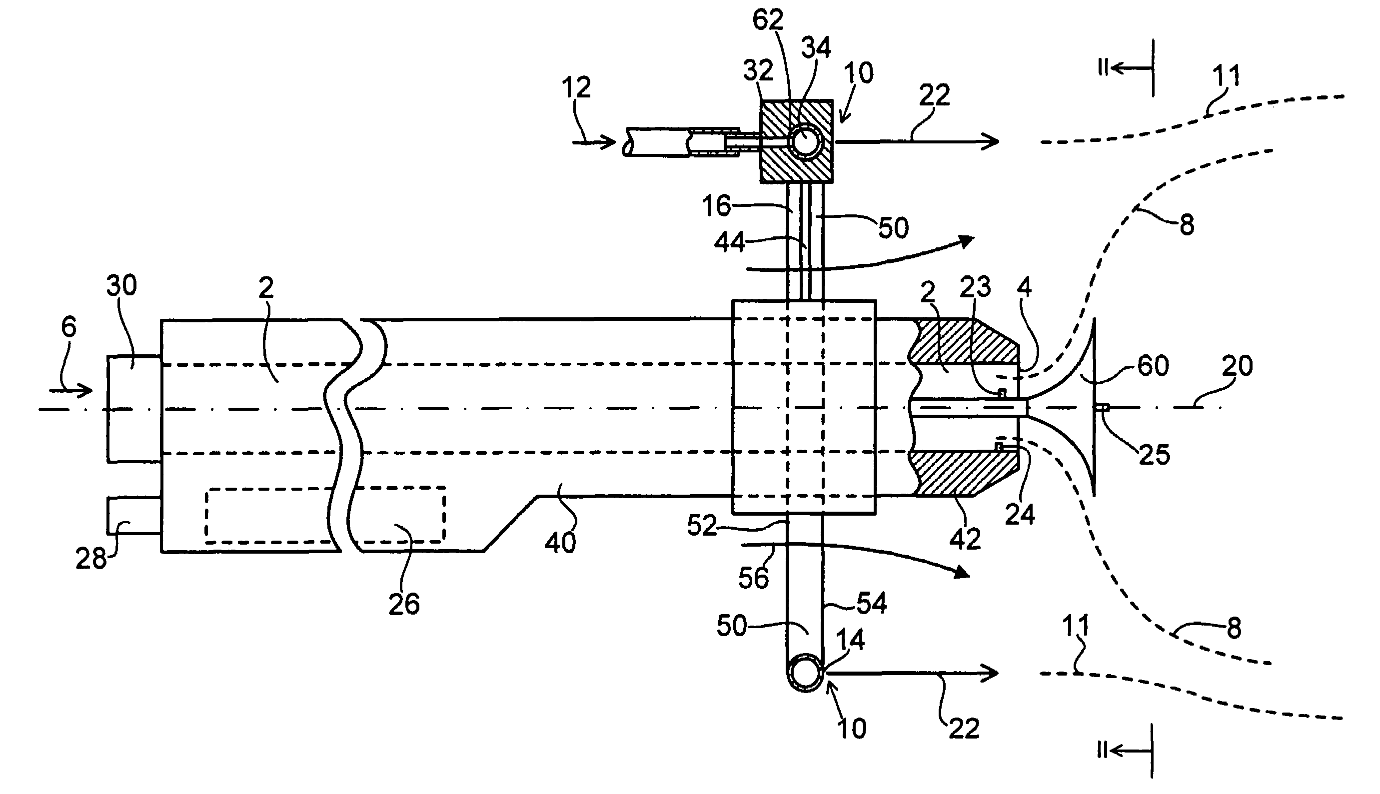
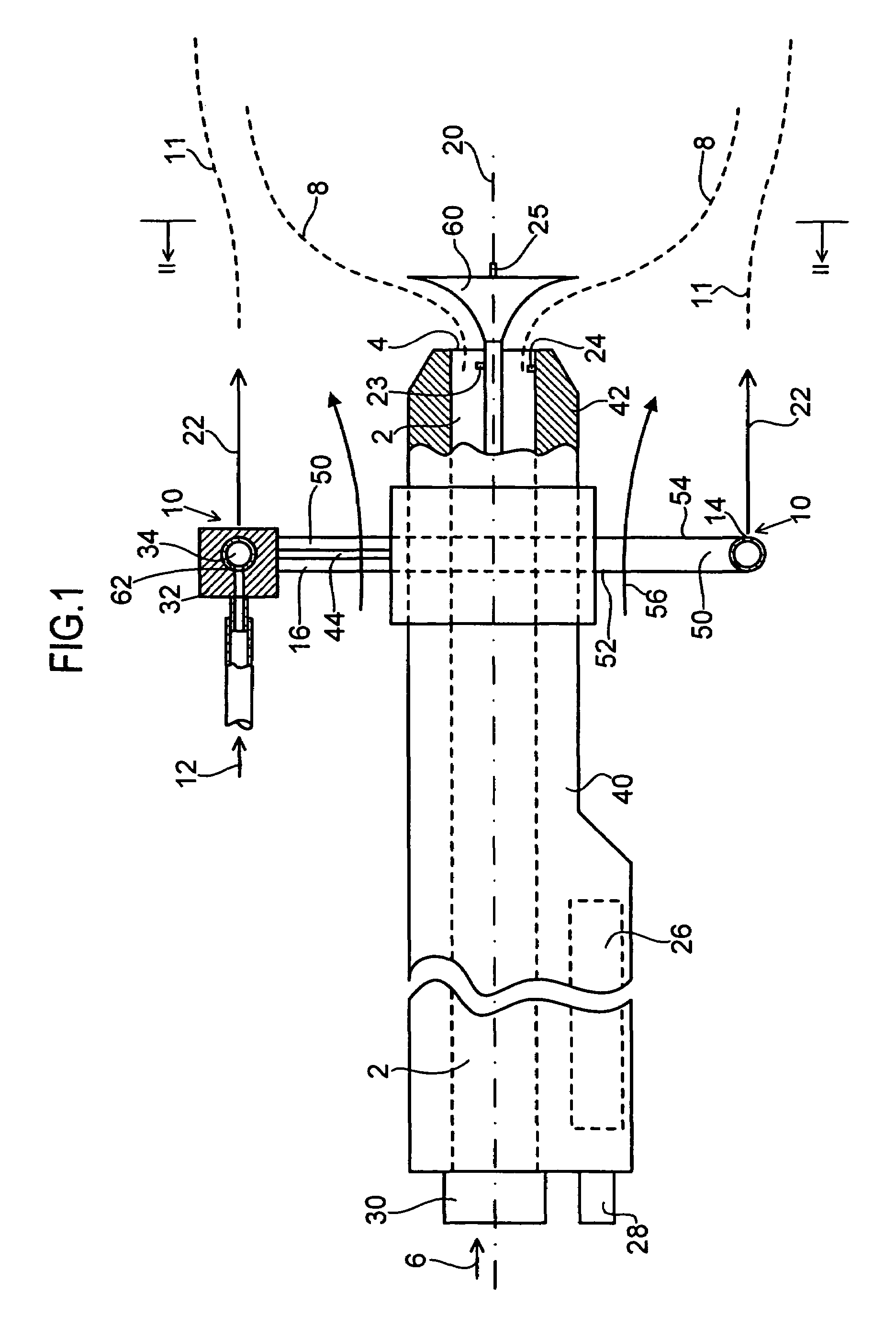
[0011]The spray apparatus shown in FIGS. 1 and 2 is designed to spray coating powder, though it may also be used to spray liquid coating materials.

[0012]The spray apparatus contains a coating material duct 2; a spray outlet 4 at the downstream end of said coating material duct 2 in order to spray the coating material 6 in the form of a flow 8 onto an (omitted) object to be coated, and a shaping air outlet 10 of compressed shaping air 12, said outlet 10 running around and apart from the flow path of the coating material 6 in order to generate from the compressed shaping air 12 a shaping air flow 11 enclosing the coating material spray jet 8.

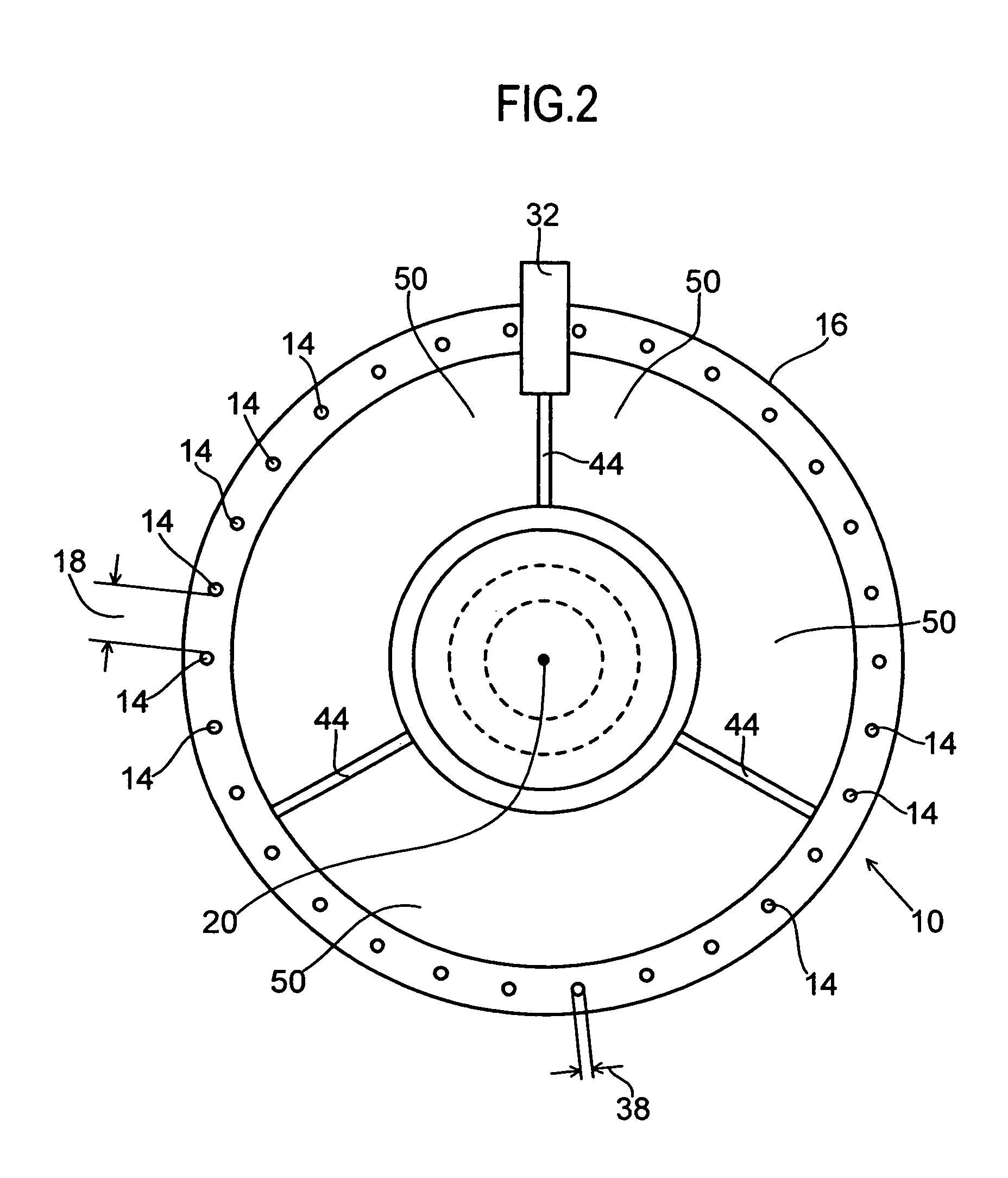
[0013]The shaping air outlet 10 consists of a large number of holes 14 through the body 16 which is undivided at said holes, these holes being distributed around and apart from the flow path of the coating material 6.

[0014]In the embodiment shown in FIGS. 1 and 2, all the holes 14 are configured at identical circumferential distances 18 from one a...


PUM


Abstract

A spray apparatus for coating material, in particular for coating powders, contains a spray outlet spraying the coating material, a shaping air outlet in the form of a plurality of holes shaping the spray jet and an ambient-air passage radially configured between the spray outlet and the holes to aspirate ambient air by means of the flow suction effect of the spray jet and / or of the shaping air flow.

Description

BACKGROUND OF THE INVENTION[0001]The present invention relates to a spray apparatus for coating materials, in particular for coating powders.[0002]In particular the present invention relates to a spray apparatus comprising at least one high-voltage electrode electrostatically charging the coating material. However it also applies to spray apparatus which are not designed to electrostatically charge coating materials.[0003]Spray apparatus of this kind are known for instance from the patent documents U.S. Pat. No. 4,324,361; DE 34 12 694 A1; U.S. Pat. Nos. 4,505,430; 4,196,465; 4,347,984 and 6,189,804.[0004]Spray apparatus fitted with shaping-air outlets of annular gap geometry incur the drawback that if said gap is supported along its longitudinal direction at several places, manufacturing constraints will preclude uniform gap size. Such a drawback however is averted by using boreholes instead of an angular gap, especially if the body containing said boreholes remains undivided at th...

Claims


Application Information

Patent Timeline
IPC IPC(8): B05B5/00A62C5/02B05B5/025B05B1/28B05B5/03B05B5/04B05B7/06B05B7/08B05B7/14B05B9/00B05C19/00
CPCB05B5/032B05B5/0407B05B5/0418B05B7/0815B05B5/0426B05B7/14
Inventor MAUCHLE, FELIXVIELI, HANSPETERMICHAEL, HANSPETER
Owner GEMA SWITZERLAND GMBH
Why Eureka
Try Eureka