Battery pack casing with lock type connector

a battery pack and lock-type technology, applied in the direction of cell components, sustainable manufacturing/processing, final product manufacturing, etc., can solve the problems of reduced welding strength between the case body and the upper cover, and large weld protrusions. , to achieve the effect of high strength, reduced thickness, and increased strength and elasticity

Active Publication Date: 2009-01-20
LG ENERGY SOLUTION LTD
View PDF1 Cites 44 Cited by
  • Summary
  • Abstract
  • Description
  • Claims
  • Application Information

AI Technical Summary

Benefits of technology

[0012]The inventors have performed various experiments and research on the structure of a battery pack, and have found that, when locking members are formed at an upper cover of the battery pack, and locking grooves are formed at a case body of the battery pack such that the locking members can be engaged in the corresponding locking grooves, the battery pack can be assembled by a mechanical coupling method, not by an ultrasonic welding method, and the battery pack can be manufactured with a high-strength material, thereby further decreasing the thickness of the battery pack.
[0015]Consequently, it is not necessary to restrict the material for the upper cover and the case body to an ultrasonic welding material. Preferably, the upper case is made of a material having higher strength and elasticity than those of the areas of the case body where the locking grooves are formed. In a preferred embodiment, the upper cover is made of stainless steel (SUS), and the case body is made of a plastic material, such as such as polycarbonate (PC) or polyacrylonitrile-butadiene-styrene (ABS). Alternatively, the case body may be made of a plastic resin only at the areas of the case body where the locking grooves are formed. When the SUS material is used as the material for the battery pack, it is possible to manufacture the battery pack having high strength with a further decreased thickness (for example, 0.1 to 0.2 mm).

Problems solved by technology

As a result, it is difficult to form the case body and the upper cover by die casting and injection molding.
Furthermore, the sizes of the weld protrusion 400a and the weld surface 300a are also decreased, and therefore, the welding strength between the case body and the upper cover is reduced, thereby increasing a welding failure rate.
However, a lithium-ion polymer battery having the structure as shown in FIG. 1 does not have an appropriate structural strength against external impacts, and therefore, use of a small-thickness case in the lithium-ion polymer battery is restricted.

Method used


Image

  • Battery pack casing with lock type connector
  • Battery pack casing with lock type connector
  • Battery pack casing with lock type connector

Examples


Embodiment Construction

[0033]Now, preferred embodiments of the present invention will be described in detail with reference to the accompanying drawings. It should be noted, however, that the scope of the present invention is not limited by the illustrated embodiments.

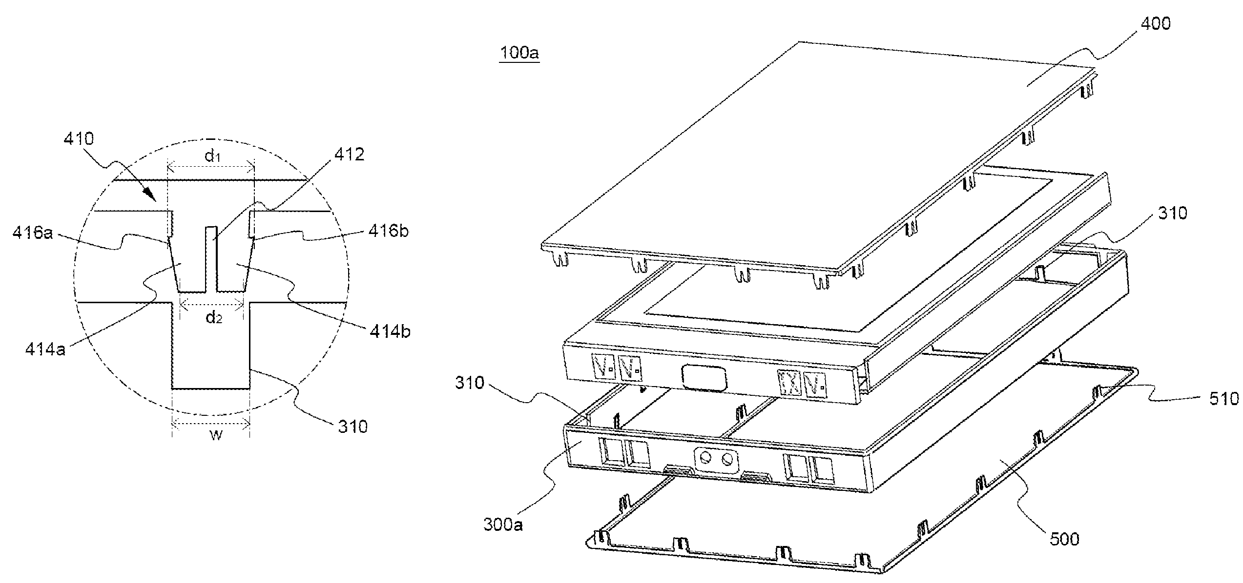
[0034]FIG. 7 is an exploded perspective view illustrating a battery pack 100 according to a preferred embodiment of the present invention before assembly.

[0035]Referring to FIG. 7, the battery pack 100 comprises: a core pack 200 having an electrode group, which includes a cathode, an anode, and a separating film, and an electrolyte mounted therein in a sealed state; a case body 300 for receiving the core pack 200; and an upper cover 400 coupled to the case body 300 for sealing the core pack 200.

[0036]The core pack 200 has a cathode tap 210 and an anode tap 220, both of which are exposed. The cathode tap 210 is connected to a protection circuit module (PCM) 600 via a cathode lead 700. The anode tap 220 is connected to the PCM 600 via an anode...


PUM

PropertyMeasurementUnit
frequencyaaaaaaaaaa
thicknessaaaaaaaaaa
thicknessaaaaaaaaaa

Abstract

Disclosed herein is a battery pack having locking members formed at an upper cover and locking grooves formed at a case body such that the locking members can be engaged in the corresponding locking grooves. The assembly of the battery pack is accomplished by a mechanical coupling method, not by an ultrasonic welding method, and the battery pack is manufactured with a high-strength material. Consequently, the battery pack can be manufactured while the thickness of the battery pack is further decreased.

Description

FIELD OF THE INVENTION[0001]The present invention relates to a locking-type battery pack, and, more particularly, to a battery pack having locking members formed at an upper cover and locking grooves formed at a case body such that the locking members can be engaged in the corresponding locking grooves, thereby enabling the assembly of the battery pack by a mechanical coupling method, not by an ultrasonic welding method, and enabling the manufacture of the battery pack with a high-strength material such that the thickness of the battery pack is further decreased.BACKGROUND OF THE INVENTION[0002]As mobile devices have been increasingly developed, and the demand of such mobile devices has increased, the demand of secondary batteries has been also sharply increased as a power source for the mobile devices. One of the secondary batteries is a lithium secondary battery having high energy density and discharge voltage, on which much research has been carried out and which is now commercia...

Claims


Application Information

Patent Timeline
Patent Type & Authority Patents(United States)
IPC IPC(8): H02J7/00H01M2/00H01M2/02H01M2/04H01M2/08H01M50/211
CPCH01M2/1061H01M10/052Y02E60/122H01M10/0565Y02E60/10H01M50/211H01M50/20H01M50/10Y02P70/50
Inventor MOON, KI EOB
Owner LG ENERGY SOLUTION LTD
Why Eureka
Try Eureka