Vehicular display device

a technology of display device and display case, which is applied in the direction of identification means, instruments, transportation and packaging, etc., can solve the problems of lack of aesthetic cosmetic appearance of the display case, and achieve the effect of excellent visibility and aesthetic cosmetic appearan

Inactive Publication Date: 2009-01-27
DENSO CORP +1
View PDF18 Cites 14 Cited by
  • Summary
  • Abstract
  • Description
  • Claims
  • Application Information

AI Technical Summary

Benefits of technology

[0011]It is an object of the present invention to provide a vehicular display device having high excellent visibility and aesthetic cosmetic appearance by improving a supporting method in consideration of the problem.
[0014]This allows the displaying unit to look floating thoroughly separately from the pointer instrument, and provides the vehicular display device having excellent visibility and aesthetic cosmetic appearance.
[0018]This allows the displaying unit to look floating thoroughly separately from the pointer instrument, and provides the vehicular display device having excellent visibility and aesthetic cosmetic appearance.

Problems solved by technology

Thus, the display device needs to simultaneously achieve two requirements of increasing the number of information items or kinds to display and of becoming small; the two requirements conflict with each other.
This involves a problem that the vehicular display device lacks aesthetic cosmetic appearance.

Method used


Image

  • Vehicular display device
  • Vehicular display device
  • Vehicular display device

Examples


first embodiment

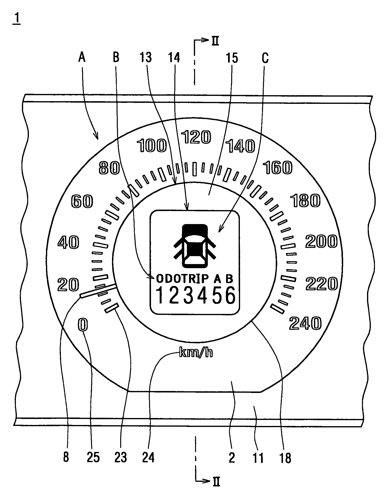
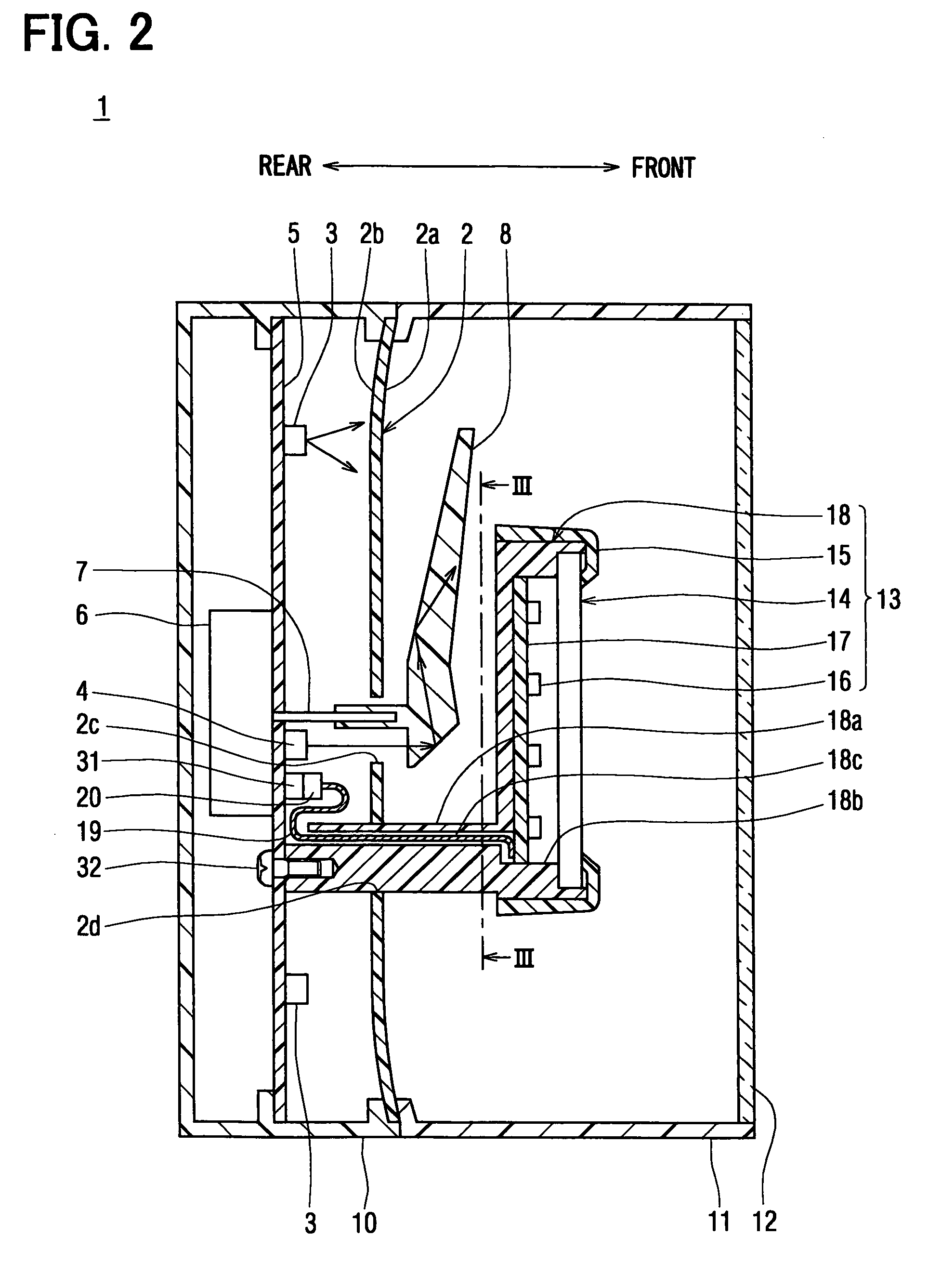
[0032]FIG. 1 is a partial front view of a combination meter 1 according to a first embodiment of the present invention. FIG. 2 is a cross-sectional view taken from line II-II in FIG. 1. In FIG. 2, the right side faces a driver's seat, from which the combination meter 1 is visible. FIG. 3 is a view illustrating an internal surface of the combination meter 1. In FIG. 3, scales 23, characters 24, and numerals 25 are eliminated for easy understanding. FIG. 4 is a diagram illustrating a structure of an electrical circuit of the combination meter 1.

[0033]The combination meter 1 is mounted in a vehicle such that a driver in a driver's seat can view the combination meter 1. The combination meter 1 displays a variety of information relating to the vehicle. The combination meter 1 includes a speedometer A that indicates a traveling speed of the vehicle, a distance meter B that indicates an accumulated traveling distance and an interval traveling distance, and a door indicator C that indicates...

second embodiment

[0067]FIG. 5 is a cross-sectional view of a combination meter 1 according to a second embodiment and corresponds to the cross-sectional view taken from line II-II in FIG. 1.

[0068]The combination meter 1 according to the second embodiment is different from that of the first embodiment in a fixation of a center panel 13 to a speedometer A.

[0069]As shown in FIG. 5, a support plate 40 is provided as a supporting unit to support and fix the center panel 13. The support plate 40 is formed of translucent material, e.g., transparent polycarbonate resin plate. The support plate 40 is closer (rightward in FIG. 5) to the viewer in a viewing direction (horizontal direction in FIG. 5) than the speedometer A or pointer 8 is. In detail, a reflector 18 fits in an engaging aperture 40a provided in the support plate 40.

[0070]The reflector 18 has a guide portion 18d substituting the attachment portion 18a of the first embodiment, as shown in FIG. 5. The guide portion 18d includes a tunnel portion 18c,...

third embodiment

[0073]FIG. 6 is a cross-sectional view of a combination meter 1 according to a third embodiment and corresponds to the cross-sectional view taken from line II-II in FIG. 1.

[0074]The combination meter 1 according to the third embodiment is different from that of the second embodiment in a structure of a support plate 40. The characters 24 and numerals 25 of the display design in the speedometer A are formed on a support plate 40

[0075]As shown in FIG. 6, characters 41 and numerals 42 are formed on a rear surface 40b of the support plate 40 by forming a non-translucent colored layer or semi-translucent colored layer using printing or hot-stamping.

[0076]Furthermore, a light emitting diode 45 is mounted on a printed circuit board 17 of a center panel 13 as a light source to illuminate the characters 41 and numerals 42, as shown in FIG. 6.

[0077]The combination meter 1 according to the third embodiment can provide the same effect as that of the first embodiment can. The center panel 13 loo...


PUM


Abstract

A center panel is closer to a viewer in the viewing direction than a speedometer A is and overlapped with the speedometer. The center panel includes an attachment portion extending from a rear side of the center panel towards a dial plate of the speedometer. The center panel is fixed to a printed circuit board of the speedometer via the attachment portion. Accordingly, when a combination meter is viewed, the attachment portion is concealed rearward of the center panel to be invisible. The center panel looks floating separately from the speedometer towards a viewer, which provides a combination meter having excellent visibility and aesthetic cosmetic appearance. Thus, a vehicular display device having excellent visibility and aesthetic cosmetic appearance can be provided by improving a method for supporting a displaying unit on a pointer instrument.

Description

CROSS REFERENCE TO RELATED APPLICATION[0001]This application is a continuation of an international patent application No. PCT / JP2005 / 3958 filed on Mar. 8, 2005 designating the United States of America, and is based on Japanese Patent Applications No. 2004-66139 filed on Mar. 9, 2004 and No. 2004-89763 filed on Mar. 25, 2004, the contents of which are incorporated herein by reference in its entirety.FIELD OF THE INVENTION[0002]The present invention relates to a vehicular display device around a driver's seat to display a variety of information to a driver.BACKGROUND OF THE INVENTION[0003]Recently, the number of information items displayed in a vehicular display device has increased. The number of components, such as an air-conditioner or an airbag, installed in a dashboard has also increased, in addition to the display device. Therefore, the display device is required to become smaller.[0004]Thus, the display device needs to simultaneously achieve two requirements of increasing the n...

Claims


Application Information

Patent Timeline
Patent Type & Authority Patents(United States)
IPC IPC(8): B60Q1/00B60K35/00B60K37/02G01D7/00G01D11/26G01D13/26
CPCB60K37/02G01D7/002G01D13/265B60K2350/1064B60K2350/203B60K2370/154B60K2370/33B60K2370/336B60K2370/6992G01D2207/30
Inventor SUMIYA, MINORUKURIKAWA, SHOJIARAKI, YOSHINORIIMAI, YUTAKAMURAMATSU, YOSHIYUKI
Owner DENSO CORP
Why Eureka
Try Eureka