
Mine clearing device incorporating unbiased motion

Inactive Publication Date: 2009-02-03
USA REPRESENTED BY THE SEC OF THE NAVY
View PDF5 Cites 6 Cited by
  • Summary
  • Abstract
  • Description
  • Claims
  • Application Information

AI Technical Summary

Benefits of technology

[0006]Accordingly, an object of the present invention is to provide an apparatus for clearing mines which is inexpensive and easy to operate.
[0007]Another object of the present invention is to provide an easily operated mine clearing device that can be used by persons, organizations, or countries with limited resources.
[0008]Another object of an embodiment of the present invention is to provide a more cost effective and simple means of marking areas traversed by a mine clearing device.
[0009]Another object of an embodiment of the present invention is to provide an apparatus for clearing mines that may be operated in areas where limited resources are available wherein the mine clearing device only requires battery power.
[0016]Accordingly, the preferred embodiment of the present invention is directed to an apparatus and process that satisfies the need for a mine clearing device that is inexpensive, easy to operate, effective and safe. The present invention is further directed to an apparatus and method which combines the simple and reliable technology of an unbiased moving, autonomous, inexpensive body with an outer surface which will resist the explosive forces of mines, and a plurality of projections on the outer shell for imparting unbiased motion, therefore providing a simple, inexpensive, but effective mine clearing device.

Problems solved by technology

There are, currently, millions of land mines remaining on the ground from past wars and scattered around dozens of countries, most of which, are poor, undeveloped countries with limited resources.
Detection and clearing of these mines is a difficult problem.
Unfortunately, these methods are extremely time-consuming and dangerous to the personnel involved.
However, these devices, although effective at clearing mines, are too expensive, too complex, and too cumbersome to deploy affordably in effective numbers throughout the world.

Method used


Image

  • Mine clearing device incorporating unbiased motion
  • Mine clearing device incorporating unbiased motion
  • Mine clearing device incorporating unbiased motion

Examples


Embodiment Construction

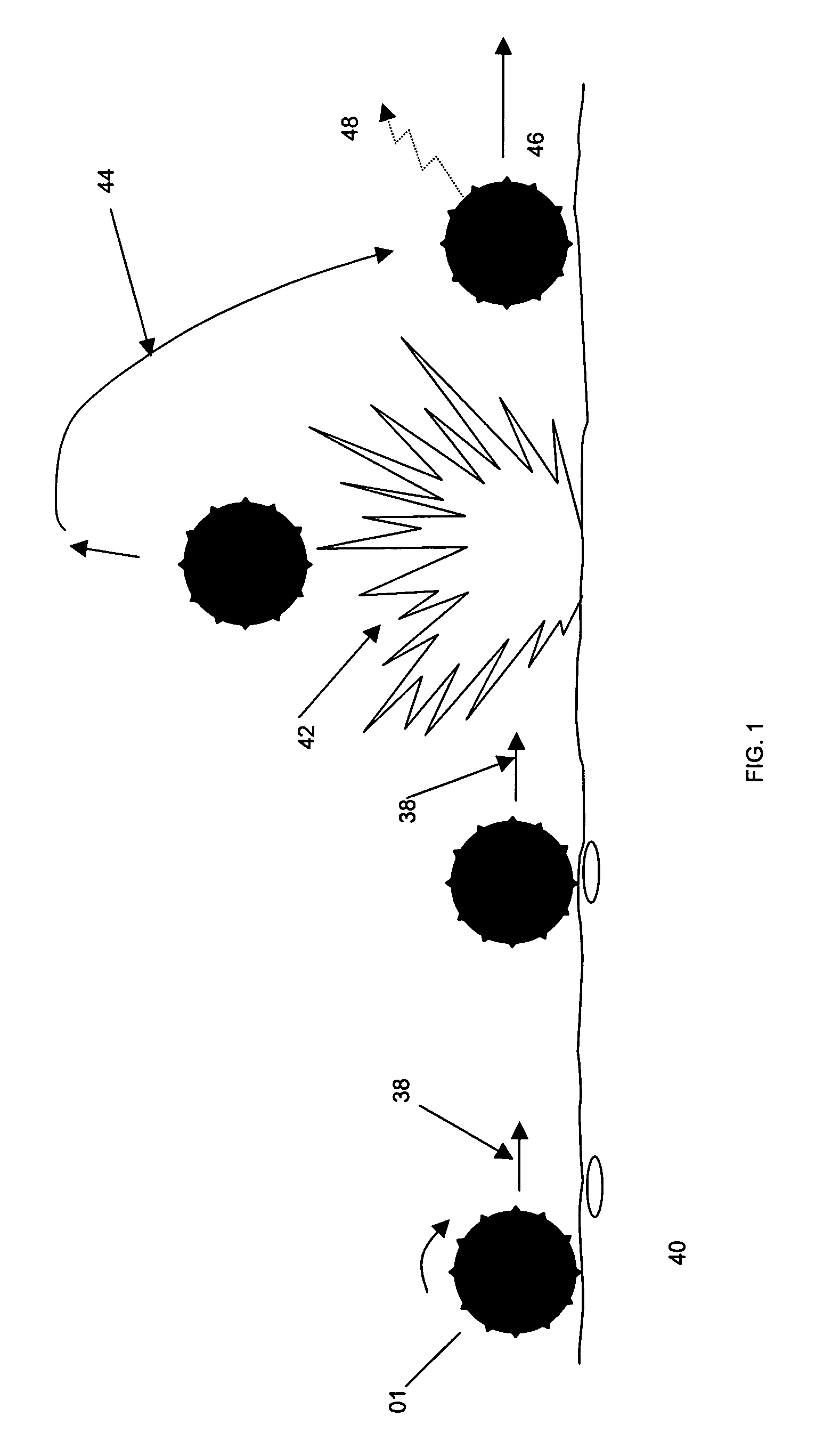
[0021]As shown in FIG. 1, the preferred embodiment of this invention comprises a mine clearing device 01 that operates by traversing a minefield (shown as step 38), encountering mines 40, exploding the mines (step 42), resisting the blast of such mines and dispersing the kinetic energy (step 44), and then continuing to traverse the minefield (step 46).

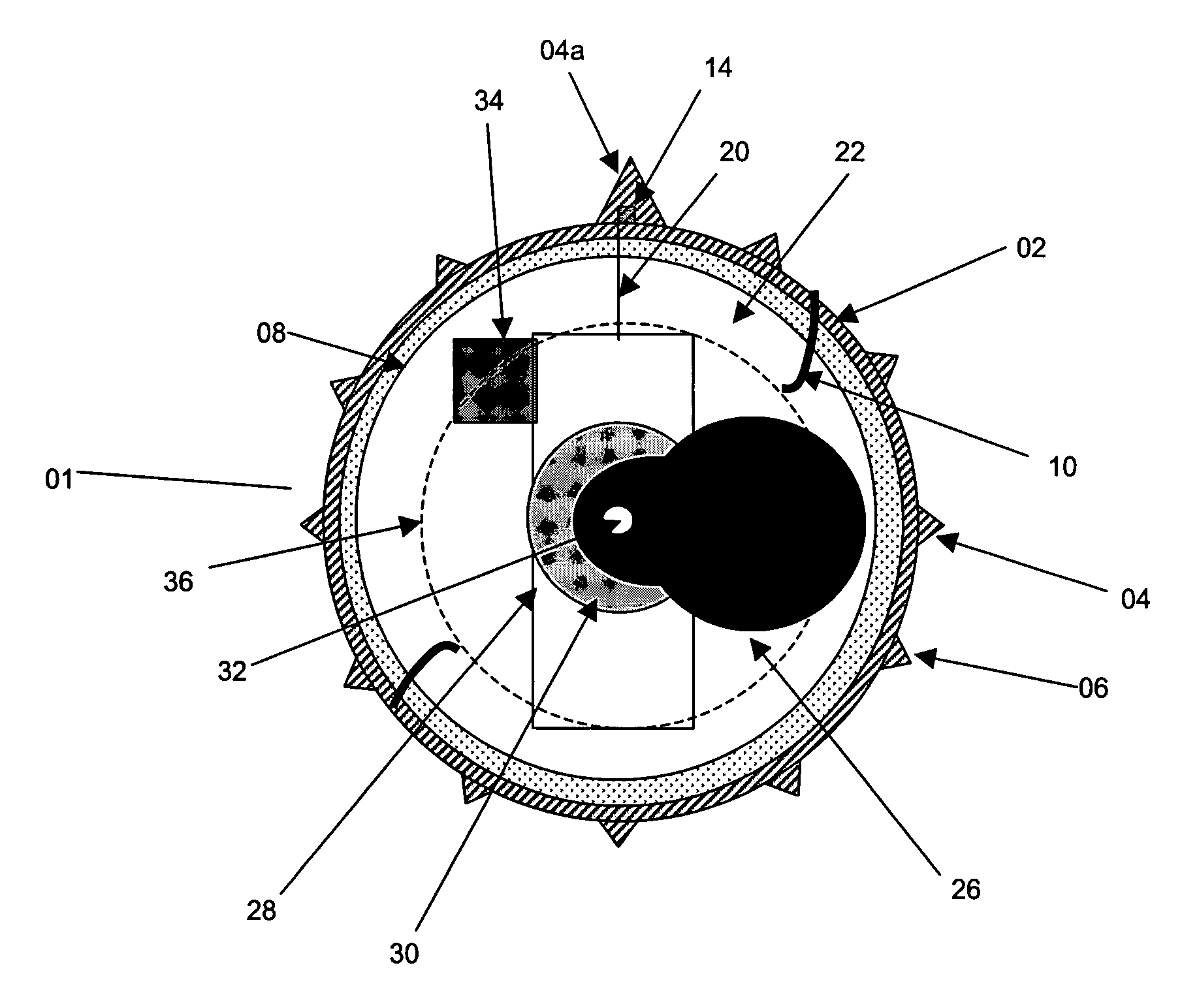
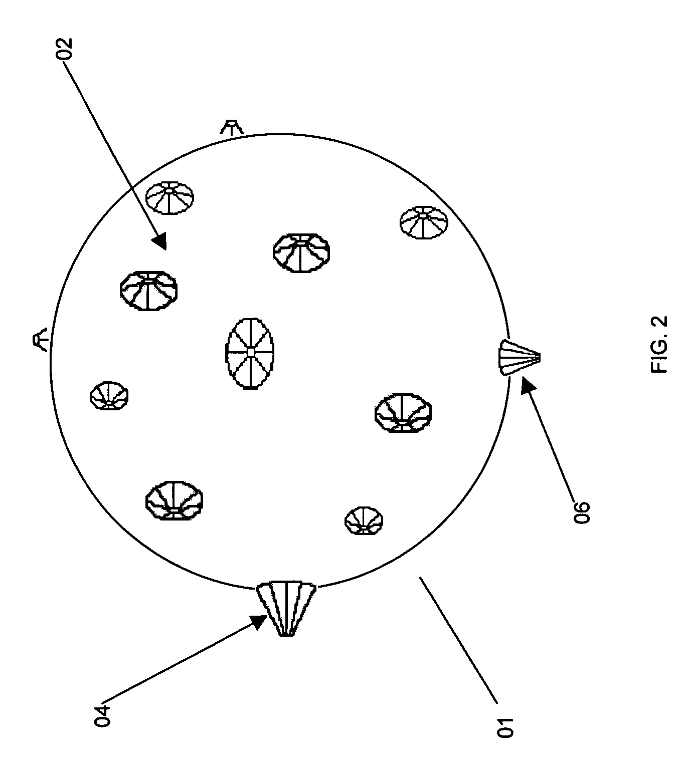
[0022]As shown in FIG. 3, mine clearing device 01 comprises a shell 02 forming a cavity 22. A plurality of anti-axial projections 04 and 06 extend from the surface of shell 02 (also shown in FIG. 2). Shell 02 contains a motor 28, which may be a direct current (DC) low voltage permanent magnet motor of either 24 or 12 volts disposed within internal cavity 22. Power source 34 is mounted inside cavity 22 and provides the necessary voltage to activate and operate the motor 28. A drive shaft 32 couples motor 28 to a ballast 26, and imparts rotational motion to ballast 26 when the motor 28 is activated. In operation, the rotational motion of...


PUM


Abstract

A mine clearing device comprises a substantially hollow body forming a cavity. An eccentric ballast is disposed within the cavity and is rotated by a motor powered by an internal power source, thereby imparting rotational motion to the device. A plurality of anti-axial projections of varying lengths and sizes are mounted on the outer surface of the body to interact with the terrain and, thus, impart unbiased motion to the body as it rotates and traverses a mine field. The outer surface of the body is made of blast resistant material. A shock absorbent material, disposed within the cavity, absorbs the explosive force of mines. Circuitry or a marker substance may be used to record or mark the path traveled by the device.

Description

STATEMENT REGARDING FEDERALLY SPONSORED RESEARCH OR DEVELOPMENT[0001]The invention claimed and disclosed herein may be manufactured and used by, or on behalf of, the Government of the United States of America for government purposes without the payment of any royalties thereon or therefor.BACKGROUND OF THE INVENTION[0002]The present invention relates generally to mine clearing devices incorporating unbiased motion, more particularly to a mine clearing device comprising a blast-resistant body and having a plurality of projections to impart unbiased motion to the device.[0003]There are, currently, millions of land mines remaining on the ground from past wars and scattered around dozens of countries, most of which, are poor, undeveloped countries with limited resources. Most of these mines are anti-personnel mines that maim rather than kill their victims. It has recently been estimated that over seventy people, mostly civilians, are injured by mines every day and that over five million...

Claims


Application Information

Patent Timeline
IPC IPC(8): F41H11/12
CPCF41H11/16F41H11/30
Inventor PORTMANN, HELMUT
Owner USA REPRESENTED BY THE SEC OF THE NAVY
Learn More