Pipe fixing system

a technology of fixing system and pipe, which is applied in the direction of couplings, machine supports, applications, etc., can solve the problems of incongruity of horizontal or vertical levels of pipes, deformation of pipes and auxiliary members used for fixing pipes, and difficulty in ensuring the safety of the pipe, so as to prevent the rise of production costs, improve the reliability of products, and uniform elasticity

Inactive Publication Date: 2009-02-03
WITHUS
View PDF6 Cites 9 Cited by
  • Summary
  • Abstract
  • Description
  • Claims
  • Application Information

AI Technical Summary

Benefits of technology

[0030]The present invention provides a pipe fixing system that can provide generally uniform elasticity to a plurality of jaws serving as wedges fixing a pipe thereto and can make the horizontal level among the plurality of jaws precisely maintained, thereby making a pipe fixed in a more rigid way and also improving the reliability of the product.
[0031]According to the present invention, furthermore, the plurality of jaws into which the pipe is mounted are rotated, and thus, even though the pipe is forcedly turned for separation, the wedge function of the plurality of jaws is not weakened, such that the pipe is not separated and damaged at all. Also, the pipe fixing system of this invention is configured in a simpler manner when compared with the existing system, thereby preventing production costs from being raised and providing a product excellent in terms of performance and quality.

Problems solved by technology

However, such the welding method has a disadvantage in that the pipe and the auxiliary members used for fixing the pipe may be all deformed due to the welding heat generated unavoidably at the time of carrying out the thermal fusion.
In addition, the process of carrying out the welding is somewhat complicated, and at the state of finishing the process, it is also found that the horizontal or vertical level of the pipe is not constant, which requires great carefulness in the process.
Moreover, in order to remove the welded pipe, the welding tools are used again or a saw is needed, such that it has disadvantages in that the pipe is not recycled and it requires lots of time and manpower for fixing and removing the pipe structure.
In the prior arts, however, the plurality of jaws are not horizontally arranged, which results in the failure of rigidly fixing the pipe.
In this case, since the jaws are not rotated at the time of rotating the pipe, the outer peripheral surface of the pipe is worn out by the friction against the toothed portions of the jaws.
Thus, the gap between the pipe and the jaws is formed such that if the pipe is pulled forcedly, it is undesirably removed.
Moreover, the outer peripheral surface of the pipe is damaged, such that the pipe can be not used again.
In the prior arts as described above, however, the pipe fixing systems, which are operated to move the jaws through the elasticity of the coil spring thus to compress the pipe, have a disadvantage in that it is difficulty to manufacture the coil spring with the uniform elasticity in large quantities.
This accompanies the problems that products do not have uniform quality and thus, bad products may be made.

Method used


Image

  • Pipe fixing system
  • Pipe fixing system
  • Pipe fixing system

Examples


first embodiment

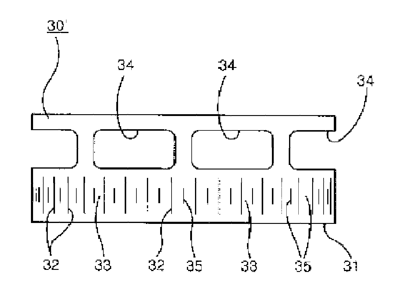
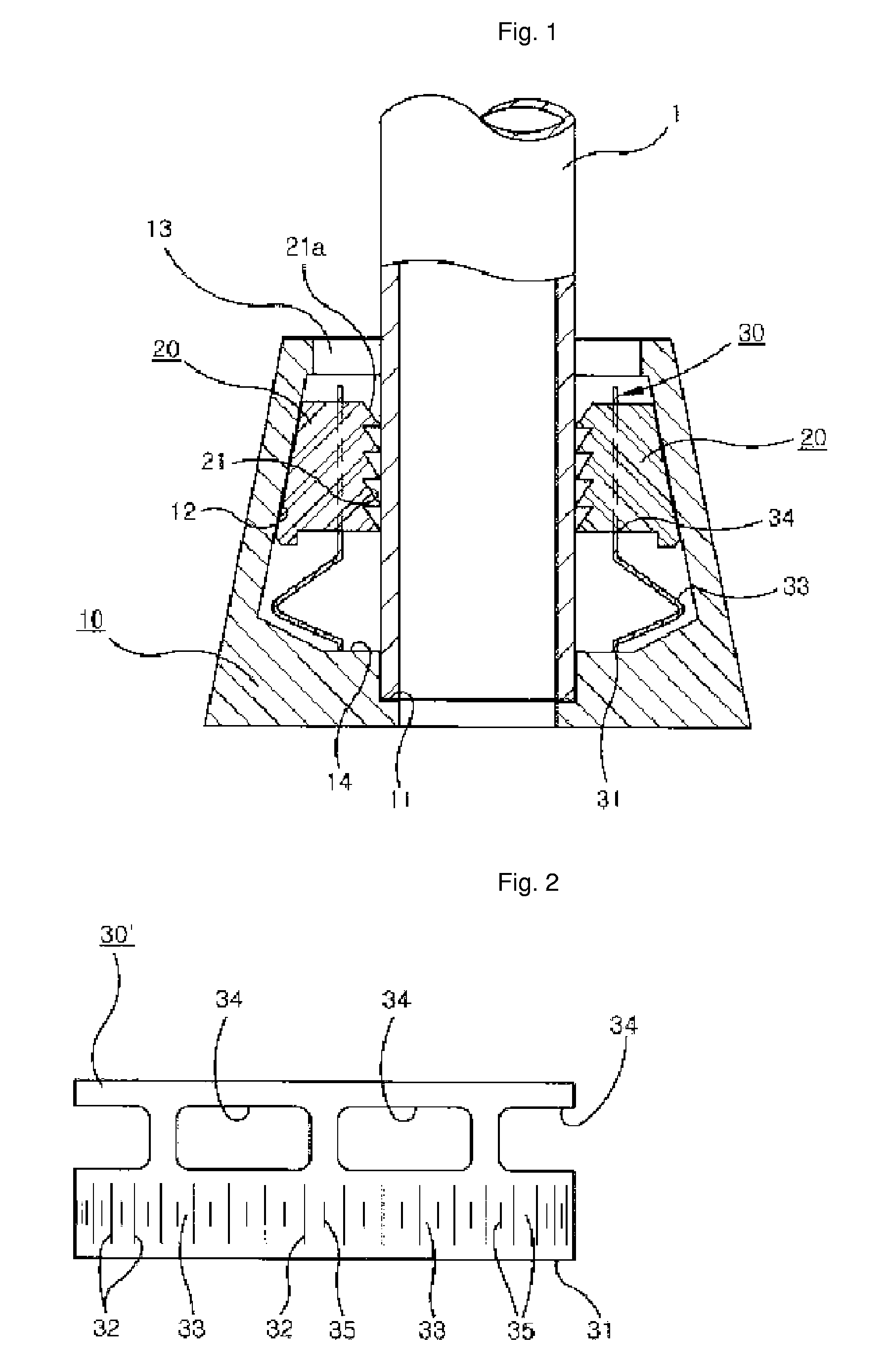
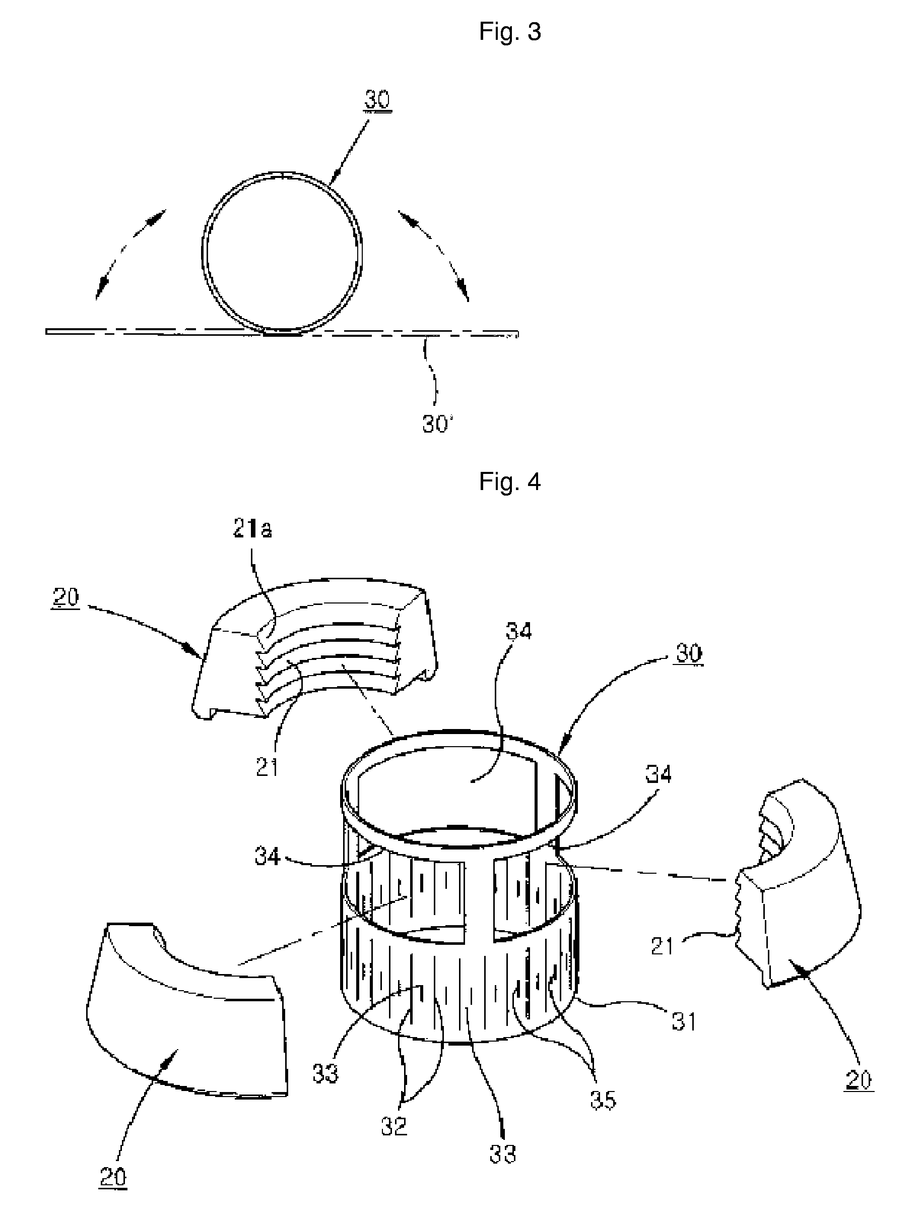
[0045]FIGS. 1 to 5 show a pipe fixing system according to the present invention.

[0046]Referring to FIG. 1, the pipe fixing system of the present invention includes a body 10, a plurality of jaws 20, and a jaw-coupling cylindrical plate spring member 30.

[0047]The body 10 is provided with a stepped part 11 formed on the lower portion of the inside thereof for stopping the movement of the end of a pipe 1 and with a tapered inner peripheral surface 12 having a diameter gradually narrowed toward the inlet thereof from the inner side thereof.

[0048]The plurality of jaws 20 are adapted to be guided to the tapered inner peripheral surface 12 of the body 10 in such a manner as to be fastened in a central direction with respect to the pipe 1 as they are moved toward an inlet 13 of the body 10 and thus to pressurize the outer peripheral surface of the pipe 1, serving as wedges in such a manner that the plurality of jaws are interposed between the tapered inner peripheral surface of the body and...


PUM


Abstract

The present invention discloses a pipe fixing system that can provide generally uniform elasticity to a plurality of jaws movably disposed along the tapered inner peripheral surface at the inside of a body thereof, thus making a pipe fixed in a more rigid way. The pipe fixing system comprises a body 10, a plurality of jaws 20 in such a manner as to be moved toward an inlet 13 of the body 10, a jaw-coupling cylindrical plate spring member 30 mounted at the inside of the body 10 in such a manner as to be supported at the lower end thereof by the inner bottom surface of the body 10. The jaw-coupling cylindrical plate spring member 30 has a plurality of cut lines 32 formed vertically from distance from the lower end thereof to the middle portion thereof in such a manner as to be equally spaced at relatively narrow intervals in a circumferential direction, a plurality of elastic piece parts 33 each formed of a plate-like shape and each disposed between the two adjacent cut lines 32 in such a manner as to be bent outwardly to provide an elastic force toward the upper portion thereof, and a plurality of coupling holes 34 formed on the upper side of the plurality of elastic piece parts 33 for inserting the plurality of jaws 20 thereinto such that the plurality of jaws 20 are kept at a horizontal level.

Description

TECHNICAL FIELD[0001]The present invention relates to a pipe fixing system, and more particularly, to a pipe fixing system that can provide generally uniform elasticity to a plurality of jaws movably disposed along the tapered inner peripheral surface at the inside of a body thereof, thus making a pipe fixed in a more rigid way.BACKGROUND ART[0002]In general, a typical method of fixing a pipe on the ground or connecting pipes with each other is welding.[0003]However, such the welding method has a disadvantage in that the pipe and the auxiliary members used for fixing the pipe may be all deformed due to the welding heat generated unavoidably at the time of carrying out the thermal fusion.[0004]In addition, the process of carrying out the welding is somewhat complicated, and at the state of finishing the process, it is also found that the horizontal or vertical level of the pipe is not constant, which requires great carefulness in the process.[0005]Moreover, in order to remove the wel...

Claims


Application Information

Patent Timeline
Patent Type & Authority Patents(United States)
IPC IPC(8): F16L3/00F16L37/08E04G21/18E04G25/04F16L19/08F16L37/00F16L37/091F16L37/092
CPCE04G21/185F16L19/08F16L37/0925F16L37/0842E04G25/04F16L37/00F16L37/08
Inventor KIM, SUKYOON
Owner WITHUS
Why Eureka
Try Eureka