
U-shaped spring energy accumulation pressurizing sealing ring

A technology of spring energy storage and pressurized sealing, which is applied in the direction of engine sealing, engine components, mechanical equipment, etc., can solve the problems of uneven elastic force, incomplete contact surface, affecting the performance of the motion system, etc., and achieve good sealing effect and deformation The effect of uniform amount and avoiding damage

Inactive Publication Date: 2014-06-11
WOTAI VALVE KUSN
View PDF0 Cites 4 Cited by
  • Summary
  • Abstract
  • Description
  • Claims
  • Application Information

AI Technical Summary

Problems solved by technology

[0005] In the prior art, adding a non-metal film to the outside of the metal spring can solve the above-mentioned problem that the two cannot be balanced, but there are still many problems
[0006] First, the metal spring is a helical spring, and the connecting parts are connected by welding, and there are overlaps. Under ultra-low temperature conditions, the solder joints may break, and there is a very big hidden danger; and compared with other parts, the overlapping parts are The elastic force provided is relatively large, resulting in uneven elastic force on the entire circumference. The metal spring hardens at low temperature, and this uneven elastic force will become more prominent and even affect the performance of the entire motion system;
[0007] Secondly, the metal spring is in the shape of a spiral, and the contact surface with the non-metallic film is not complete. Under the extrusion of the elastic force and the medium force, it will leave indentations on the inner wall of the non-metallic film, making the film wall thickness uneven, resulting in The shrinkage rate of the film at low temperature is not uniform, and the parts that cannot be supported by the spring are very likely to become leak points

Method used


Image

  • U-shaped spring energy accumulation pressurizing sealing ring

Examples


Embodiment

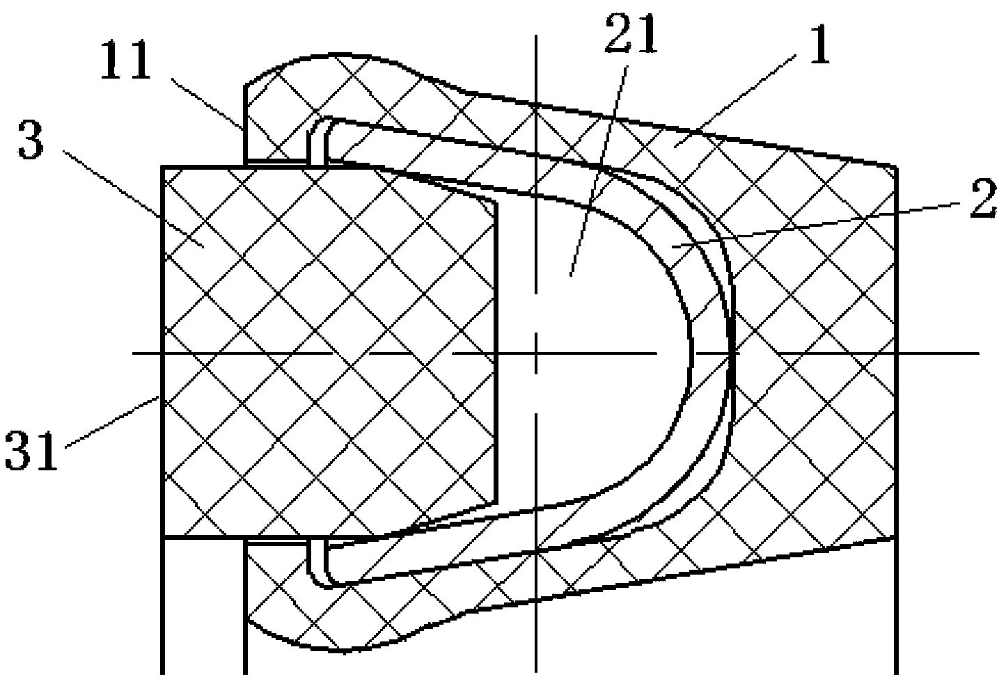
[0020] Embodiment: A U-shaped spring energy-storage pressurized sealing ring, which is composed of a non-metallic sheath 1, a metal U-shaped ring 2 and a back-up ring 3, wherein the cross-section of the metal U-shaped ring is U-shaped, and the The inner space of the metal U-shaped ring forms a U-shaped groove 21, the open end of the metal U-shaped ring faces the sealed medium side or the pressure side, and the non-metallic coating covers the metal U-shaped ring The outer surface of the non-metallic covering sleeve has a sealing end face 11 parallel to the opening end face of the metal U-shaped ring, the retaining ring is filled in the U-shaped groove of the metal U-shaped ring, and the The exposed surface 31 of the retaining ring parallel to the open end surface of the metal U-shaped ring is higher than the sealing end surface 11 of the non-metallic sheath.

[0021] The present invention uses a special stainless steel metal U-shaped ring as the skeleton, and is covered with a ...


PUM


Abstract

The invention discloses a U-shaped spring energy accumulation pressurizing sealing ring, which consists of a nonmetal covering sleeve, a metal U-shaped ring and a baffle ring, wherein the cross section of the metal U-shaped ring is in a U shape, in addition, a U-shaped groove is formed in an inner space of the metal U-shaped ring, the opening end surface of the metal U-shaped ring faces one side or the pressure side of a sealed medium, the non metal covering sleeve covers outside the metal U-shaped ring, in addition, the nonmetal covering sleeve has a sealing end surface parallel to the opening end surface of the metal U-shaped ring, the baffle ring is plugged into the U-shaped groove of the metal U-shaped ring, and in addition, the outwards exposed surface, parallel to the opening end surface of the metal U-shaped ring, of the baffle ring is higher than the sealing end surface of the nonmetal covering sleeve. The U-shaped spring energy accumulation pressurizing sealing ring is mainly used in low-temperature (below -110 DEG C) and ultra-low-temperature (-196 DEG C to -256 DEG C) environment, can be used for static sealing and dynamical sealing, and is particularly applicable to low-temperature high-pressure environment.

Description

technical field [0001] The invention belongs to the field of seals for piston systems or pressure systems, in particular to a U-shaped sealing ring structure that can be used in low temperature (below -110°C) and ultra-low temperature (-196 to -256°C) environments. Background technique [0002] At present, the existing international and domestic sealing ring products of the same type are only suitable for static sealing, low pressure and end face sealing. The sealing ring used for dynamic sealing, the metal skeleton is a coil spring, and there are solder joints at the interface, which has hidden dangers under low temperature conditions. [0003] At ultra-low temperatures, rubber O-rings can harden or even crack and cannot be used; metal O-ring or C-ring seals cannot provide adequate compensation for rod and piston shrinkage. [0004] Under ultra-low temperature conditions, both metal and non-metal will shrink, and the shrinkage rate of non-metal parts is generally about ten...

Claims


Application Information

Patent Timeline
IPC IPC(8): F16J15/00
Inventor 于成亮邹宁金凤禄张键伟谢挺
Owner WOTAI VALVE KUSN
Learn More