Available input-output power estimating device for secondary battery
a technology of available input-output power and secondary batteries, applied in the field of estimating power, can solve problems such as sub>inevitably contain errors
- Summary
- Abstract
- Description
- Claims
- Application Information
AI Technical Summary
Benefits of technology
Problems solved by technology
Method used
Image
Examples
first embodiment
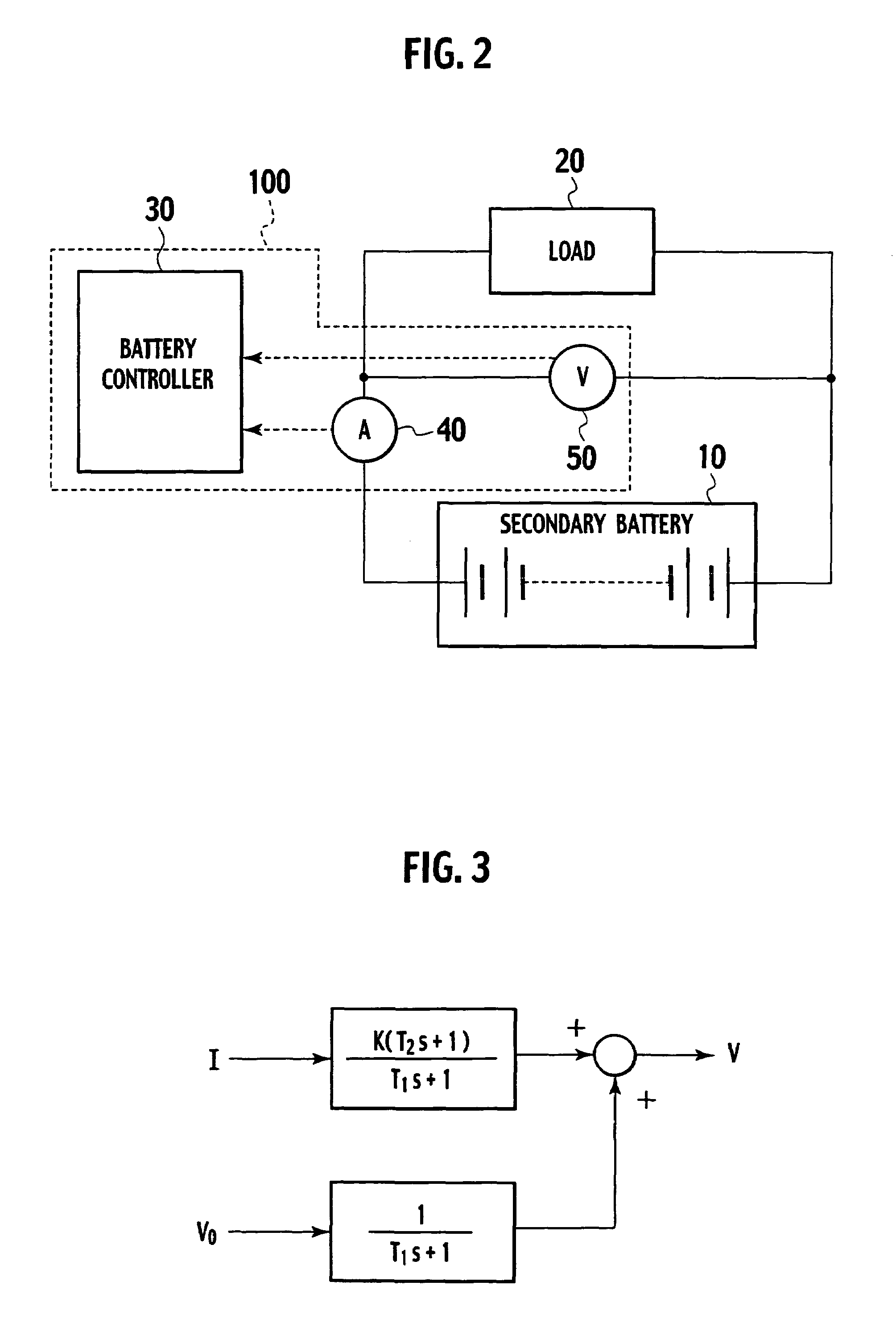
[0047]FIG. 3 is a view showing a battery model of a secondary battery of a first embodiment.
[0048]Although this battery model is a reduction (primary) model without particular separation in positive and negative electrodes, this battery model is sufficient to illustrate charging and discharging characteristics of an actual secondary battery. In this figure, I represents current [A] (with a positive value representing a charging period while a negative value represents a discharging period); V a terminal voltage [V]; V0 an open circuit voltage [V] (also called an electromotive force or an open circuit voltage); K internal resistance; T1 and T2 time constants; and s a Laplace operator (or Laplace variable).
[0049]This battery model is represented by
[0050]V=K(T2s+1)T1s+1I+1T1s+1V0.(11)
[0051]Since Eq. (11) is a special case of Eq. (7) where both the denominators A(s) and C(s) of the first and second terms on the right side in Eq. (7) take A(s)=C(s)=T1s+1, Eq. (11) well describes a ...
second embodiment
[0109]A second embodiment is configured such that the lowpass filter treatment is executed on the components K(k)T2(k), T1(k) of the value {right arrow over (θ)}(k) of the parameter vector {right arrow over (θ)}(or components (â^n, {circumflex over (b)}n,) in the battery model shown in FIG. 7), which are associated with the direct term, obtained in the first embodiment.
[0110]The second embodiment differs from the first embodiment in respect of step S100 in the flowchart of operations in the first embodiment shown in FIG. 5 and is similar thereto in other respect. Therefore, description of the other respect is herein omitted.
[0111]Since the components K(k)T2(k) and T1(k) of the value {right arrow over (θ)}(k) of the parameter vector {circumflex over (θ)} are easily affected by noise, the presently filed embodiment is configured to execute filter treatment on these components K(k)T2(k) and T1(k) by using a lowpass filter operator given as
[0112]G(s)=1τs+1.(39)
[0113]Then, Eq. (30) is...
third embodiment
[0122]A third embodiment is configured such that the lowpass filter treatment is executed on a ratio
[0123]T1(k)T2(k)
of the components K(k)T2(k) and T1(k) of the value {right arrow over (θ)}(k) of the parameter vector {right arrow over (θ)} (or (ân, {circumflex over (b)}n)) in the battery model shown in FIG. 7), which are associated with the direct term obtained in the first embodiment.
[0124]The third embodiment differs from the first embodiment in respect of step S100 in the flowchart of the operations in the first embodiment, shown in FIG. 5, and is similar thereto in other respect. Therefore, description of the other respect is herein omitted.
[0125]Although the components K(k)T2(k) and T1(k) in the value {circumflex over (θ)}(k) of the parameter vector {right arrow over (θ)} calculated in step SS60 are easily affected by noise, variation of the value K(k) of internal resistance K, a steady state gain, is small. Therefore, in the presently filed embodiment, the filter treatment i...
PUM
| Property | Measurement | Unit |
|---|---|---|
| time constant T1 | aaaaa | aaaaa |
| time constant T1 | aaaaa | aaaaa |
| current | aaaaa | aaaaa |
Abstract
Description
Claims
Application Information
 - R&D
- Intellectual Property
- Life Sciences
- Materials
- Tech Scout
- Unparalleled Data Quality
- Higher Quality Content
- 60% Fewer Hallucinations
Browse by: Latest US Patents, China's latest patents, Technical Efficacy Thesaurus, Application Domain, Technology Topic, Popular Technical Reports.
© 2025 PatSnap. All rights reserved.Legal|Privacy policy|Modern Slavery Act Transparency Statement|Sitemap|About US| Contact US: help@patsnap.com


