Reflected wave power estimation device in a radar signal processor

a radar signal processor and power estimation technology, applied in the direction of measurement devices, multi-channel direction-finding systems using radio waves, instruments, etc., can solve problems such as difficulty in embodied, and achieve the effect of shortening the tim

Active Publication Date: 2009-02-03
DENSO CORP
View PDF10 Cites 15 Cited by
  • Summary
  • Abstract
  • Description
  • Claims
  • Application Information

AI Technical Summary

Benefits of technology

[0089]According to this aspect of the invention, the adjacent azimuth array response matrix, limiting elements to the reflected waves in the azimuths adjacent to each other, is used, so that the order of the inverse matrix when obtaining the signal covariance matrix (Sf) can be made smaller and the computing volume can be reduced. This aspect of the invention is optimum for the radar signal processor of the vehicle-mounted radar apparatus to which arithmetic processing in a shorter time is expected although high-function CPU capacity can not be used therefor.
[0091]According to this aspect of the invention, the reflected waves to be used as the elements of the adjacent azimuth array response matrix are limited to a predetermined number of the reflected waves adjacent to the reflected wave power of which is to be estimated, so that the adjacent azimuth array response matrix can be easily computed and determined. Besides, the computing volume by the CPU (computer) can be reduced, and a tradeoff between simplification of computing and increase of errors can be adjusted by adjusting the number of the reflected waves to be selected.
[0093]According to this aspect of the invention, the reflected waves to be used as the elements of the adjacent azimuth array response matrix are limited to ones which exist within a predetermined azimuth difference with respect to the reflected wave power of which is to be estimated, so that the adjacent azimuth array response matrix can be easily computed and determined. Besides, the computing volume by the CPU (computer) can be reduced, and a tradeoff between simplification of computing and increase of errors can be adjusted by properly adjusting a value of the difference of the azimuth.
[0095]According to this aspect of the invention, the reflected waves to be used as the elements of the adjacent azimuth array response matrix are limited to ones meeting such a condition that the inner product between the array response vectors of the reflected wave to be obtained and the reflected wave power of which is to be estimated is a predetermined value or more, so that the computing volume by the CPU (computer) can be reduced, and a tradeoff between simplification of computing and increase of errors can be adjusted.
[0097]According to this aspect of the invention, the caught reflected waves are classified, and the powers of the reflected waves belonging to each group can be estimated for each group, so that the power of the reflected wave can be estimated within a shorter time even if there are a lot of reflected waves.

Problems solved by technology

In estimation of power according to the maximum likelihood method with Expression 11, but, it may be difficult to embody because of the operation of inverse matrix with large computation.

Method used


Image

  • Reflected wave power estimation device in a radar signal processor
  • Reflected wave power estimation device in a radar signal processor
  • Reflected wave power estimation device in a radar signal processor

Examples


first embodiment

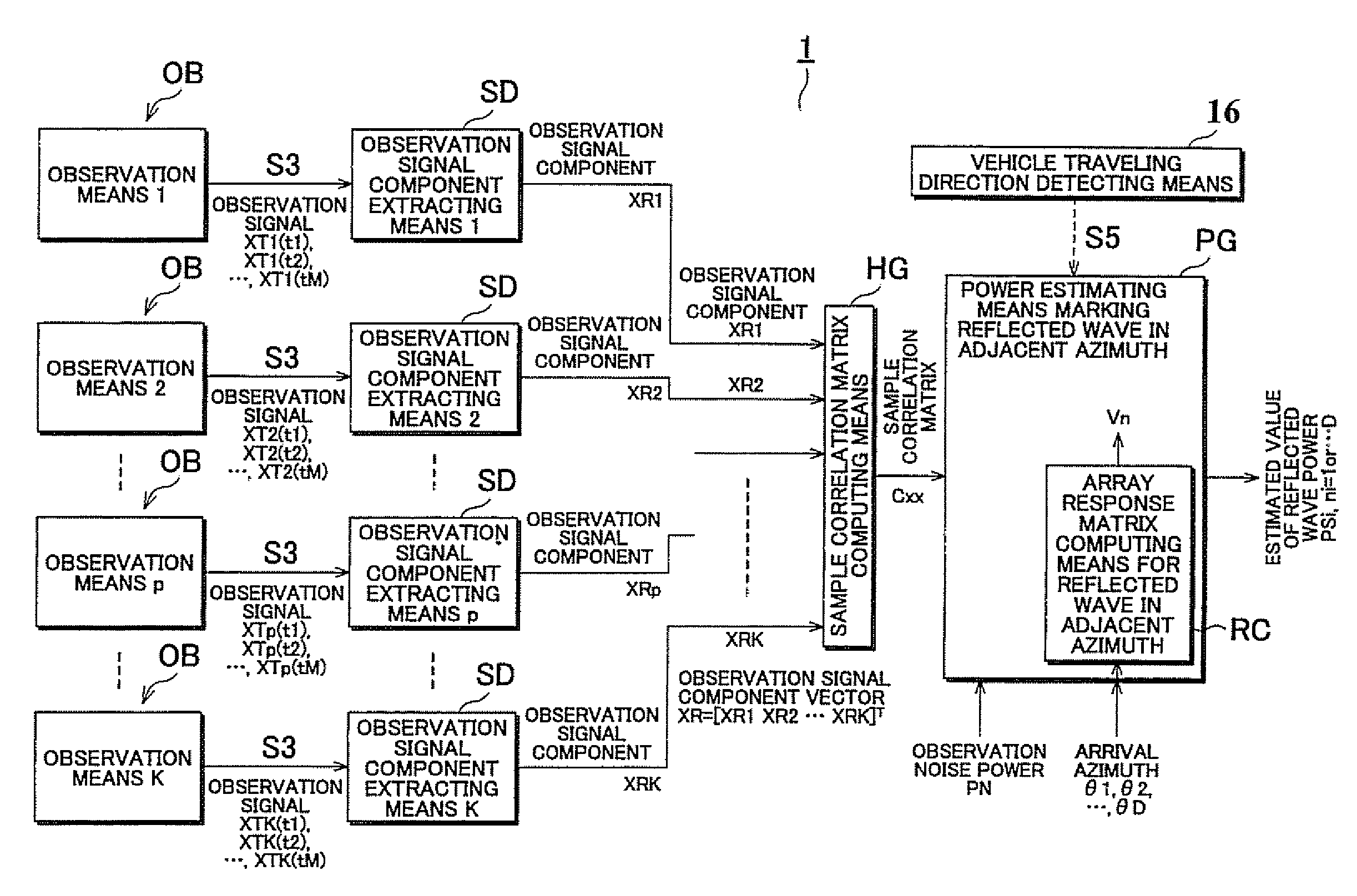
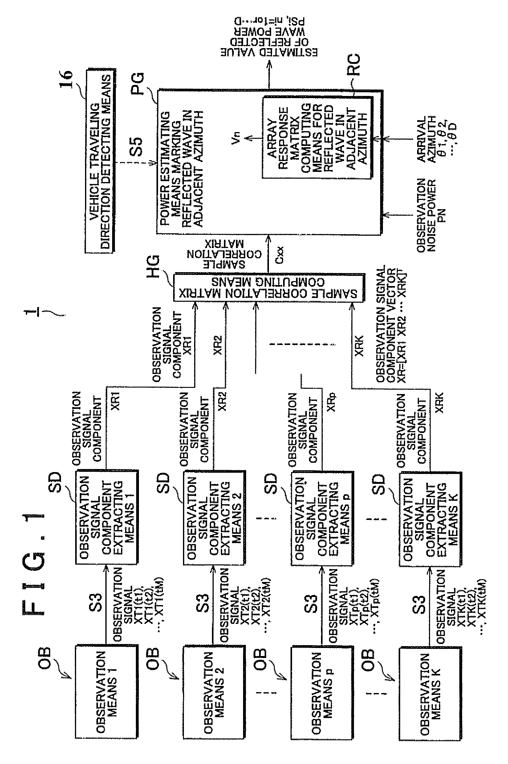
[0098]The vehicle-mounted array radar apparatus 1 is comprised of the observation means OBs: 1 through K, the observation signal component extracting means SDs: 1 through K, the sample correlation matrix computing means HG and the power estimating means marking reflected wave in adjacent azimuth PG, as shown in FIG. 1. The array radar apparatus 1 may be provided with a vehicle traveling direction detecting means 16 for computing a traveling direction of a vehicle from an angle of a steering or positioning information of a GPS, connecting with the power estimating means marking reflected wave in adjacent azimuth PG, if necessary. Respective blocks in FIG. 1 only shows functions exercised by the array radar apparatus 1, and do not always means individual hardwares. Each block, or two or more functioning blocks which are united with each other may be operated through a computer and program executed thereby on the basis of a predetermined operation clock by a multi-task with a passage o...

second embodiment

[0140]Another embodiment of the invention is explained hereinafter. A schematic structure of this embodiment is similar to one of the embodiment of FIG. 1. And, structural elements excluding the array response matrix computing means for reflected wave in adjacent azimuth RC inside the power estimating means marking reflected wave in adjacent azimuth PG are similar to ones in the embodiment of FIG. 1, so that the explanation is omitted.

[0141]In this aspect of the invention, the array response matrix computing means for reflected wave in adjacent azimuth RC selects a predetermined number Th of the reflected waves in order of adjacence to the reflected wave i which is a subject for power estimation, and determines the array response matrix for reflected wave in adjacent azimuth Vn having these array response vectors as elements.

[0142]For instance, when the azimuth of the reflected wave is θ1=0.0°, θ2=5.0°, θ3=14.0°, and θ4=−10.0° and Th=2, the case of estimation of the power of the ref...

third embodiment

[0144]Another embodiment of the invention is explained hereinafter. A schematic structure of this embodiment is similar to one of the embodiment of FIG. 1. And, structural elements excluding the array response matrix computing means for reflected wave in adjacent azimuth RC inside the power estimating means marking reflected wave in adjacent azimuth PG are similar to ones in the embodiment of FIG. 1, so that the explanation is omitted.

[0145]In this aspect of the invention, the array response matrix computing means for reflected wave in adjacent azimuth RC selects the reflected waves approximating a predetermined azimuth difference Δθ with respect to a reflected wave i which is a subject for power estimation, that is, the reflected waves which exist within a predetermined azimuth difference Δθ with respect to the reflected wave i, and determines the array response matrix for reflected wave in adjacent azimuth Vn having these array response vectors as elements.

[0146]For instance, when...


PUM


Abstract

A radar signal processor has observation means for outputting a predetermined observation signal from a reflected wave, means for extracting an observation signal component concerning a target from the observation signal, means for computing a sample correlation matrix showing a correlation characteristic between the observation means from the observation signal components, means for estimating power of the reflected wave from the sample correlation matrix, and an array response matrix which is comprised of response vectors of the reflected waves. When estimating the power, an adjacent azimuth array response matrix having only the reflected waves of a predetermined arrival direction which power is to be estimated and the reflected waves of an azimuth adjacent to the reflected wave as elements is determined so as to estimate the power of the reflected wave.

Description

[0001]This application claims benefit of priority to Japanese Patent Application No. 2005-345709 filed on Nov. 30, 2005.BACKGROUND OF THE INVENTION[0002]This invention relates to a radar signal processor suitable for a vehicle-mounted array radar apparatus having two or more antenna components.[0003]A conventionally known vehicle-mounted array radar apparatus judges presence or velocity of a preceding target which exists in a forward direction by estimating a power of a reflected wave from the target in order to prevent a collision and maintain the inter-vehicle distance with respect thereto (see a Japanese patent application publication number of which is 2004-198218).[0004]A power estimating portion of such kind of the vehicle-mounted array radar apparatus may have two or more observation means, observation signal component extracting means, a sample correlation matrix computing portion, and a power estimating means according to maximum likelihood method.[0005]A conventional array...

Claims


Application Information

Patent Timeline
Patent Type & Authority Patents(United States)
IPC IPC(8): G01S7/02G01S13/93G01S13/931G01S7/32
CPCG01S13/42G01S13/931G01S3/74G01S2013/0245
Inventor TAKANO, GAKUYAMANO, CHIHARUNATSUME, KAZUMAMIYAKE, YASUYUKI
Owner DENSO CORP
Why Eureka
Try Eureka