[0008]Briefly, the present invention provides an element object model and a
vector graphics markup language for accessing that element object model in a manner that allows
program code developers to consistently interface with a scene graph
data structure to produce graphics. The vector graphics markup language comprises an interchange format for expressing vector graphics via the element object model. When interpreted, the markup is parsed into data including elements in an element tree that is translated into the objects of a scene graph data structure. At the element tree level, a property
system and presenter
system are provided to provide rich programmability features, including inheritance characteristics and eventing, making it straightforward for scene designers to design possibly complex scenes. In general, the vector graphics elements correspond to shape elements and other elements including image and video elements that correlate with scene graph objects of the scene graph object model. The properties and other resources of the vector graphics elements also correlate with similar properties and resources the scene graph object model.
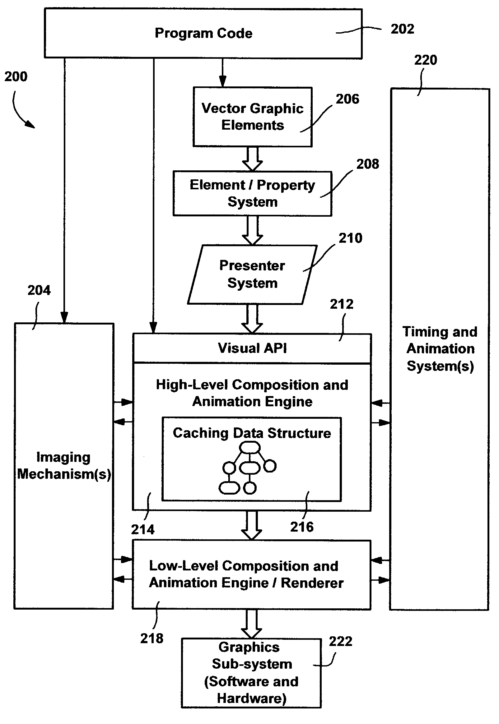
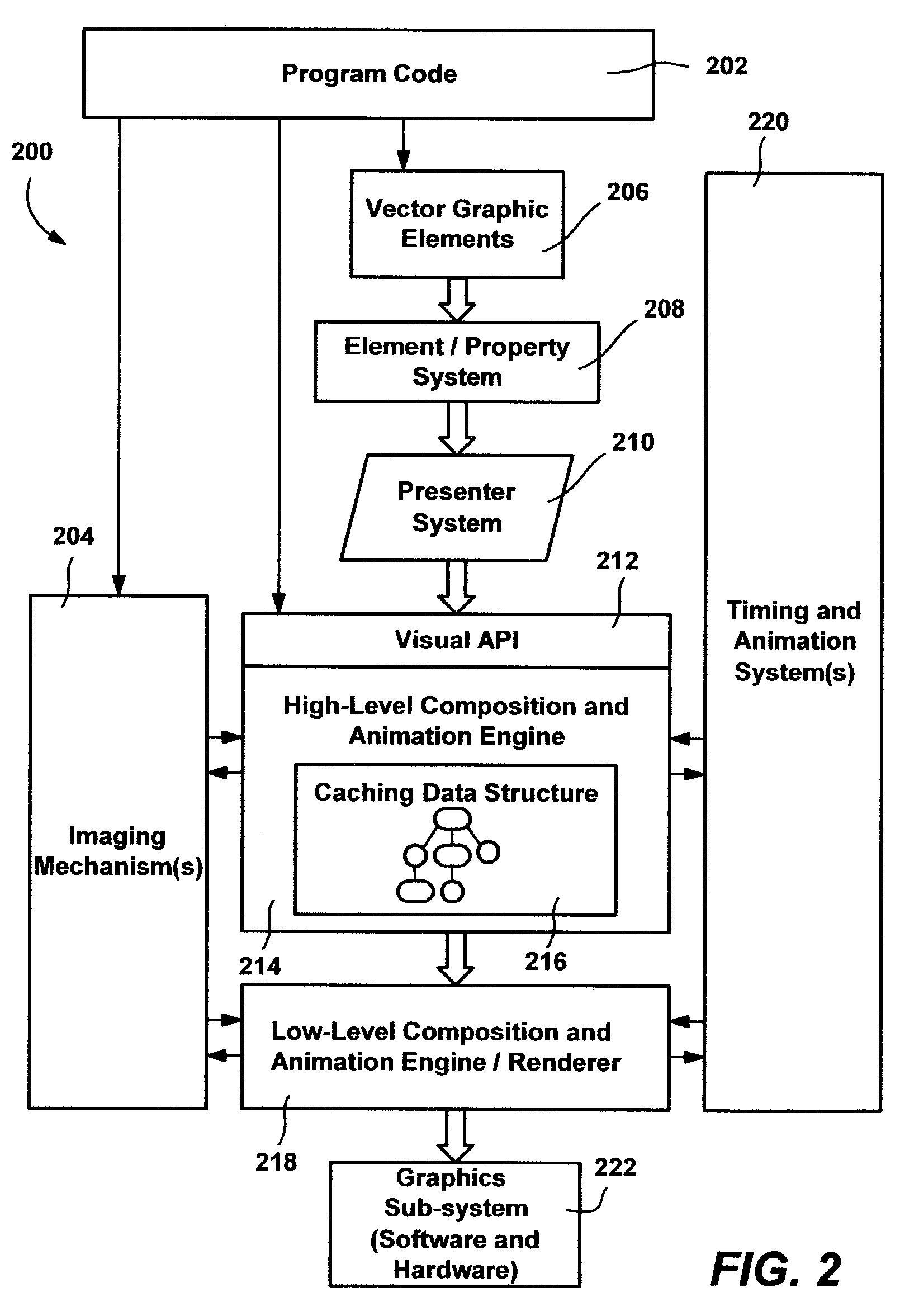
[0009]The vector graphics
system can thus program to an element level, in which each of the drawing shapes is represented as an element at the same level as the rest of the programmable elements in a page / screen, allowing interaction with the presenter system, events and properties. The vector graphics system also provides a mechanism for
programming to a resource level, by which scene designers can essentially shortcut the element tree and presenter system and program directly to the visual API layer that interfaces with the scene graph data structure. This provides a more efficient and lightweight way to output the appropriate object, although losing of some of the programmability of the element level. In one implementation, when a fill of type “visual
brush” is programmed, the parser can directly call the API layer with resource
level data to create a corresponding visual paint object (which is also a correlation between the element object model and the scene graph object model). In this two-tiered system, element level vector graphics get parsed into created elements, which need later translation to the objects, while resource level vector graphics get parsed and directly stored in an efficient manner. At the same time, the resource
level data or the objects created thereby can be referenced by elements and part of the element tree. To this end, elements including visual paint elements may be named. The scene designer thus has the ability to balance efficiency against programmability as needed.
[0010]The element
class hierarchy includes a shape class, an image class, a video class and a canvas class. Elements of the shape class include rectangle, polyline, polygon, path, line and
ellipse. Each element may include or be associated with fill (property) data,
stroke data, clipping data, transform data,
filter effect data and
mask data. Shapes correspond to geometry (of the scene graph object model) that is drawn with inherited and cascaded presentation properties that are used to construct the pen and the
brush needed to draw the shapes. The image class is more specific than a shape and can include more raster
graphical data, while the video class allows video (or similar
multimedia) to be played within a displayed element. The canvas class may act as a container for shapes, to keep shapes lightweight.
[0012]The markup language provides distinct ways to describe an element, including a simple string format or a complex object notation (a complex property
syntax). For a simple string format, the parser / translator and / or presenter system uses a type converter for converting a string to an appropriate visual API object. When the fill attribute is too complex to fit into a single string, complex property
syntax, which may be inline in the markup, is used to describe the property set. Because the same rendering model is shared between the element level and the API level, many of the objects are the same, which makes
parsing / translation highly efficient and provides other benefits. A resource instance also may be located elsewhere (e.g., in the markup or a file), and referenced by a name. In this manner, a scene designer can reuse an element in the element tree throughout a scene, including elements described by the complex property syntax.

