Multifunction data port providing an interface between a digital network and electronics in residential or commercial structures

a multi-functional, data port technology, applied in the field of data ports, can solve the problem that no prior art discloses a utility meter or data por

Inactive Publication Date: 2009-02-03
BOH TECH
View PDF84 Cites 54 Cited by
  • Summary
  • Abstract
  • Description
  • Claims
  • Application Information

AI Technical Summary

Benefits of technology

[0027]Yet another object of the invention is to provide a data port which provides a secure banking and Internet browsing capability.

Problems solved by technology

None of the prior art discloses a utility meter or data port which provides an interface between a digital service network and home electronics.

Method used


Image

  • Multifunction data port providing an interface between a digital network and electronics in residential or commercial structures
  • Multifunction data port providing an interface between a digital network and electronics in residential or commercial structures
  • Multifunction data port providing an interface between a digital network and electronics in residential or commercial structures

Examples


first embodiment

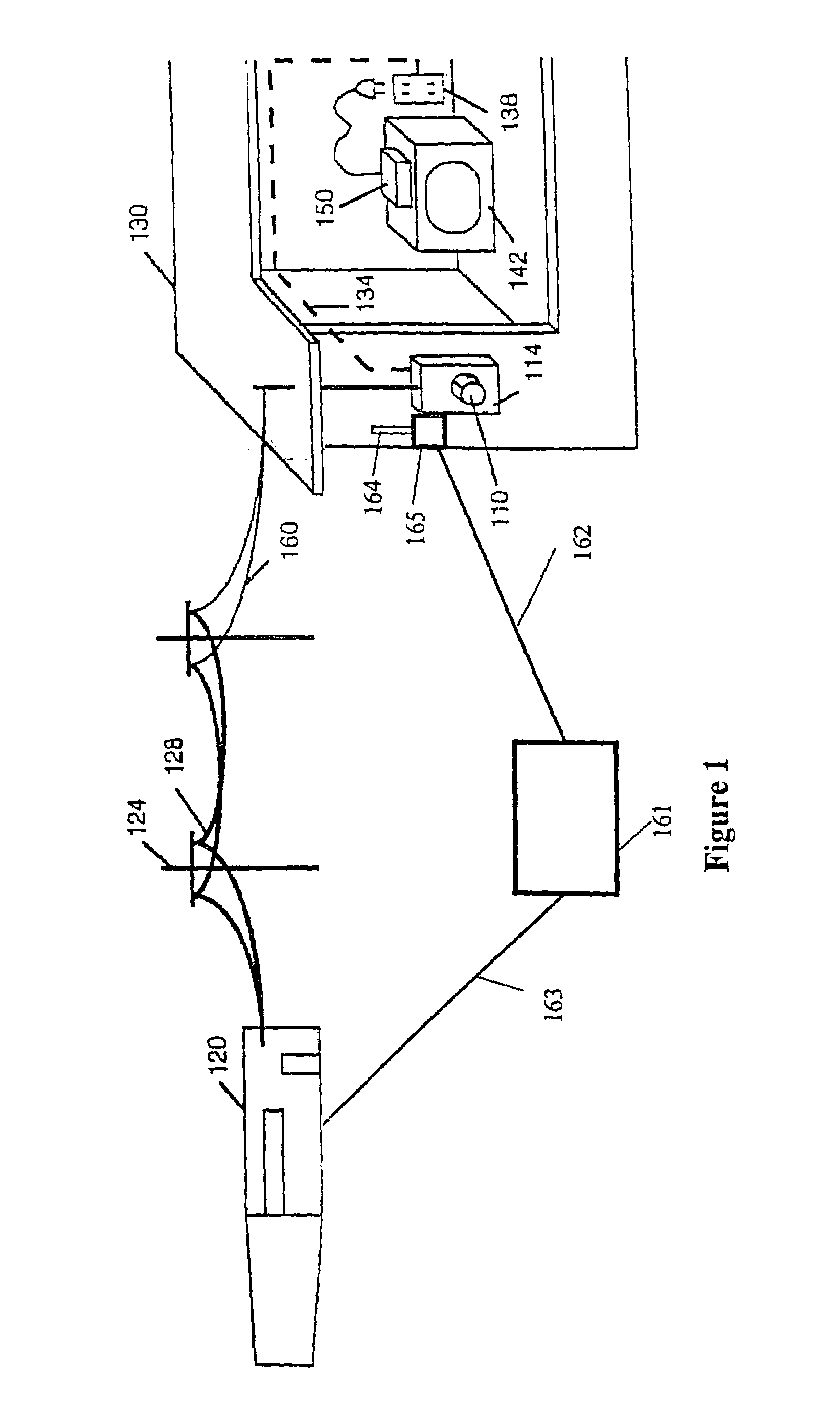
[0045]FIG. 1 shows an electric meter 110 according to the invention mated to a standard meter box 114. An electric company 120 provides electrical service to a house 130 over external power lines 128 suspended by utility poles 124. Alternatively, the electric company 120 may provide electrical service to the house 130 via power lines buried under the ground.

[0046]According to the invention, electric company 120 provides a digital service network over a network communication line 160, which may be, for example, fiber optic cable, coaxial cable or twisted pair cable. The electric meter 110 provides an interface between the digital service network and the internal house wiring 134. Internal house wiring 134 may include, for example, power lines, telephone lines, and television coaxial cables. A device 150 can plug into a wall outlet 138 to access the digital service network. Device 150 may, for example, provide video signals to television 142.

[0047]As previously discussed, the electric...

second embodiment

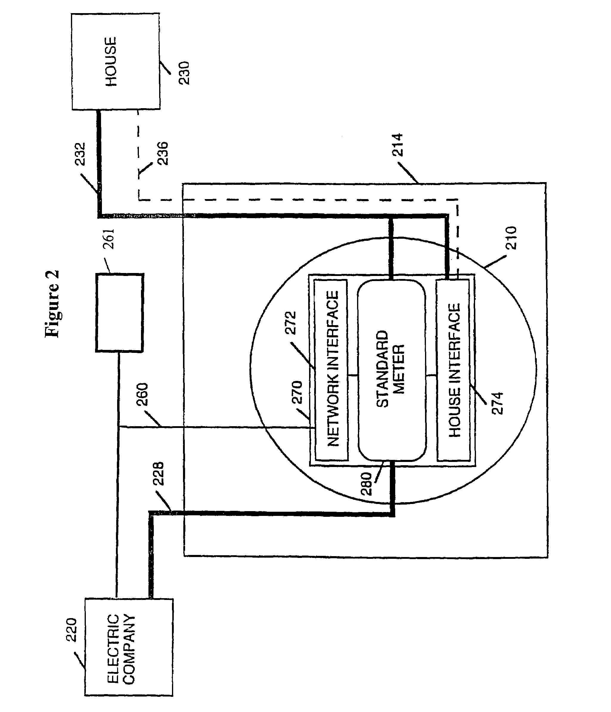
[0051]FIG. 2 shows a block diagram of second embodiment of an electric meter 210 according to the invention providing an interface between an electric company 220 which provides a digital service network over network communication line 260 and a house 230. The gateway meter 210 is coupled to the sealed meter box 214 and has a computer 270. Computer 270 is connected to network communication line 260 through a network interface 272. Computer 270 also includes a house interface 274 and a standard electric power meter 280, both of which are coupled with network interface 272. Network interface 272 and house interface 274 may comprise signal-processing computers.

[0052]Electric company 220 supplies electrical power over external power lines 228 which are connected to standard electric power meter 280 and house's internal power lines 232. House interface 274 is also coupled to house's internal power lines 232 for communication thereon. House interface 274 is further optionally coupled to t...

third embodiment

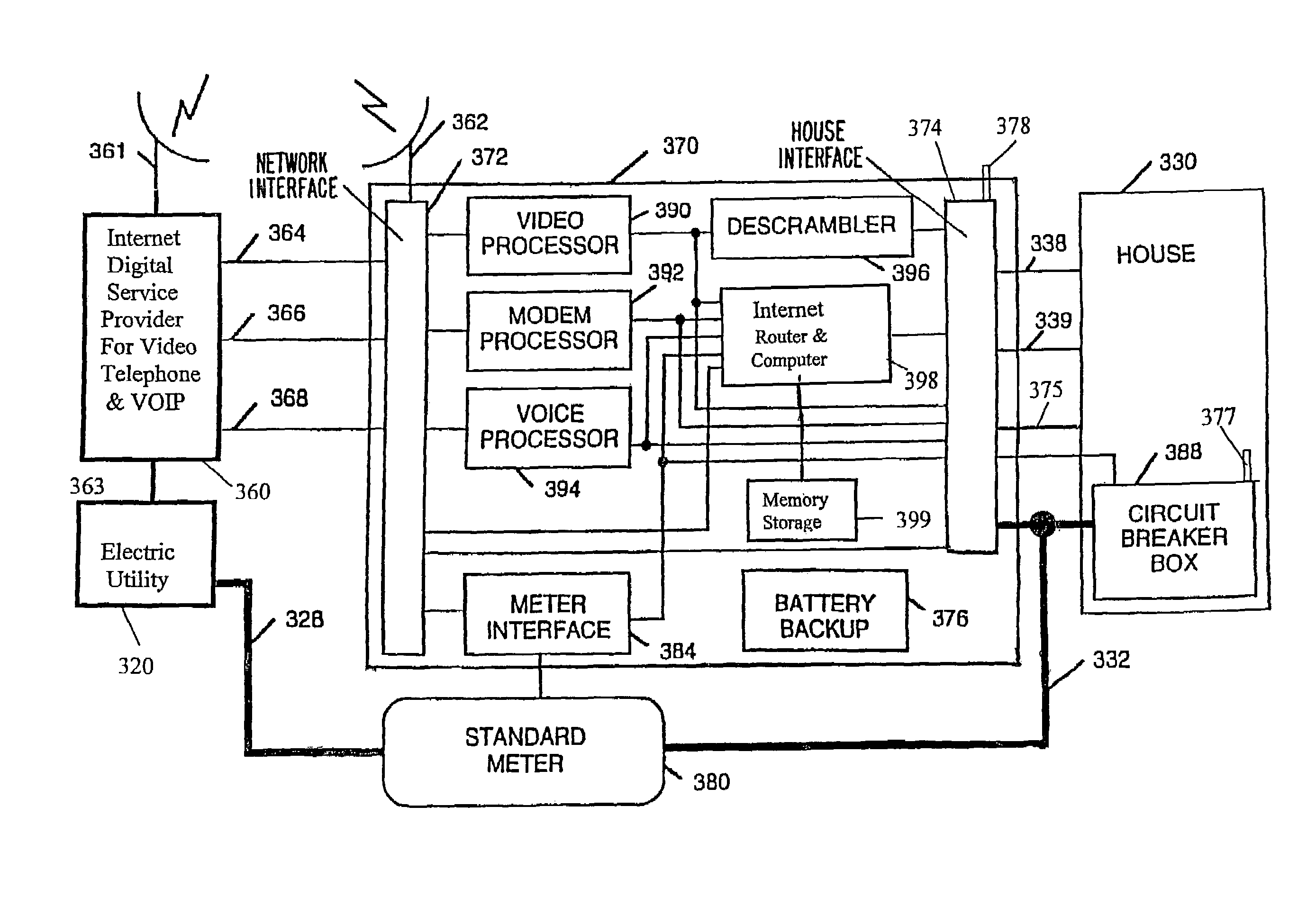
[0057]FIG. 3 shows associated electronics for an electric meter according to the invention with a detailed block diagram of a signal processing computer 370 which provides an interface between an electric company 320 and a house 330. The computer 370 is located in the electric meter (not shown). The electric company 320 provides digital data services via network wireless transmission device 361 and over fiber optic cables 364, coaxial cables 366, and twisted pair cables 368, or directly over power lines 328. The computer 370 is coupled to the digital data services through network interface 372.

[0058]Network interface 372 provides a remote wireless transmission device 362 to communicate with network wireless transmission 361. Such communication might include transmitting and receiving signals over a selected microwave frequency channel. Data transmission on the selected frequency channel might include such techniques as token ring data transmission, spread spectrum transmission, and / ...


PUM


Abstract

A multifunction data port is located in or attached to the utility meter or the meter box. The installation or removal of the data port requires opening the meter seal. The data port interface can provide broad band access to a digital network and the Internet. It can provide the utility customer with a secure computer terminal for commerce and telecommunications. It can provide the electric utility load management and time of use metering of electrical power.

Description

RELATED APPLICATIONS[0001]The present application is a continuation-in-part of U.S. national phase patent application Ser. No. 09 / 508,998, filed May 18, 2000, now abandoned based on international application number PCT / US97 / 16426, filed Sep. 17, 1997, from which priority is claimed; and a continuation-in-part of U.S. provisional patent application Ser. No. 60 / 155,069, filed Sep. 21, 1999, from which priority is claimed.BACKGROUND OF THE INVENTION[0002]1. Field of the Invention[0003]The invention is related to a data port and, more particularly, to a multifunction intelligent data port having a computer interface between a digital service network and a utility user's home electronics. The invention further relates to remote utility meter reading and remote load management.[0004]2. Related Art[0005]A customer of an electric company typically has an electric meter located at the customer's structure or site of distribution of electrical power. The customer's structure may be, for examp...

Claims


Application Information

Patent Timeline
Patent Type & Authority Patents(United States)
IPC IPC(8): H04M1/64G08C19/16G06F17/00G06F15/16G01R21/00
CPCG01D4/008G06Q20/102G06Q50/06Y02B90/247Y04S20/50Y04S50/12Y04S10/54Y04S10/50Y02B90/20Y04S20/30
Inventor ROOS, CHARLES E.
Owner BOH TECH
Why Eureka
Try Eureka