Friction stir welding of joints with shims

a friction stir welding and joint technology, applied in the direction of soldering apparatus, manufacturing tools, auxillary welding devices, etc., can solve the problems of reducing the quality of the finished structure, gaps or mismatches, etc., to facilitate the formation of a desired contour and improve the quality of the joints formed

Active Publication Date: 2009-02-10
THE BOEING CO
View PDF17 Cites 20 Cited by
  • Summary
  • Abstract
  • Description
  • Claims
  • Application Information

AI Technical Summary

Benefits of technology

[0007]The present invention provides a method of friction stir welding skin members and substructures and a structural assembly formed by such welding operations. For example, the structural assembly can be welded with a shim disposed in a space defined between a skin member and the substructure or between two adjacent skin members, to thereby friction stir weld the members of the assembly via the shim. Thus, the shim facilitates the formation of a desired contour of the assembly, and is further capable of improving the quality of the joints formed between the multiple members of the assembly.
[0009]According to another embodiment of the present invention, there is provided a friction stir welded structural assembly that includes a substructure defining an outer contour, one or more skin members disposed on the substructure at the outer contour of the substructure, and at least one shim disposed between the skin members or between the skin member and the substructure. At least one friction stir weld joint connects the shim to the adjacent skin member(s) and or the substructure. The skin members and substructures can be rigid members, which can be formed of aluminum or other materials, and each can define a simple or complex geometric configuration. Further, skin members can be welded to opposite sides of the substructure. For example, the outer contour of the substructure and, hence, the assembly, can define an airfoil or other aerospace shape.

Problems solved by technology

Nevertheless, even small differences between the configuration of the formed skins and the underlying support structure can complicate the assembly or reduce the quality of the finished structure.
Small gaps or mismatches can result between the skin and the framework and / or between the different portions of the skin that are connected to the support framework.
Such gaps are typically filled with putty or caulk, but the strength, durability, and / or corrosion resistance of the connections can be affected.

Method used


Image

  • Friction stir welding of joints with shims
  • Friction stir welding of joints with shims
  • Friction stir welding of joints with shims

Examples


Embodiment Construction

[0022]The present invention now will be described more fully hereinafter with reference to the accompanying drawings, in which some, but not all embodiments of the invention are shown. Indeed, this invention may be embodied in many different forms and should not be construed as limited to the embodiments set forth herein; rather, these embodiments are provided so that this disclosure will satisfy applicable legal requirements. Like numbers refer to like elements throughout.

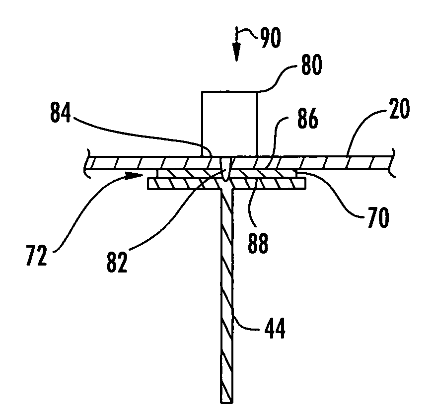
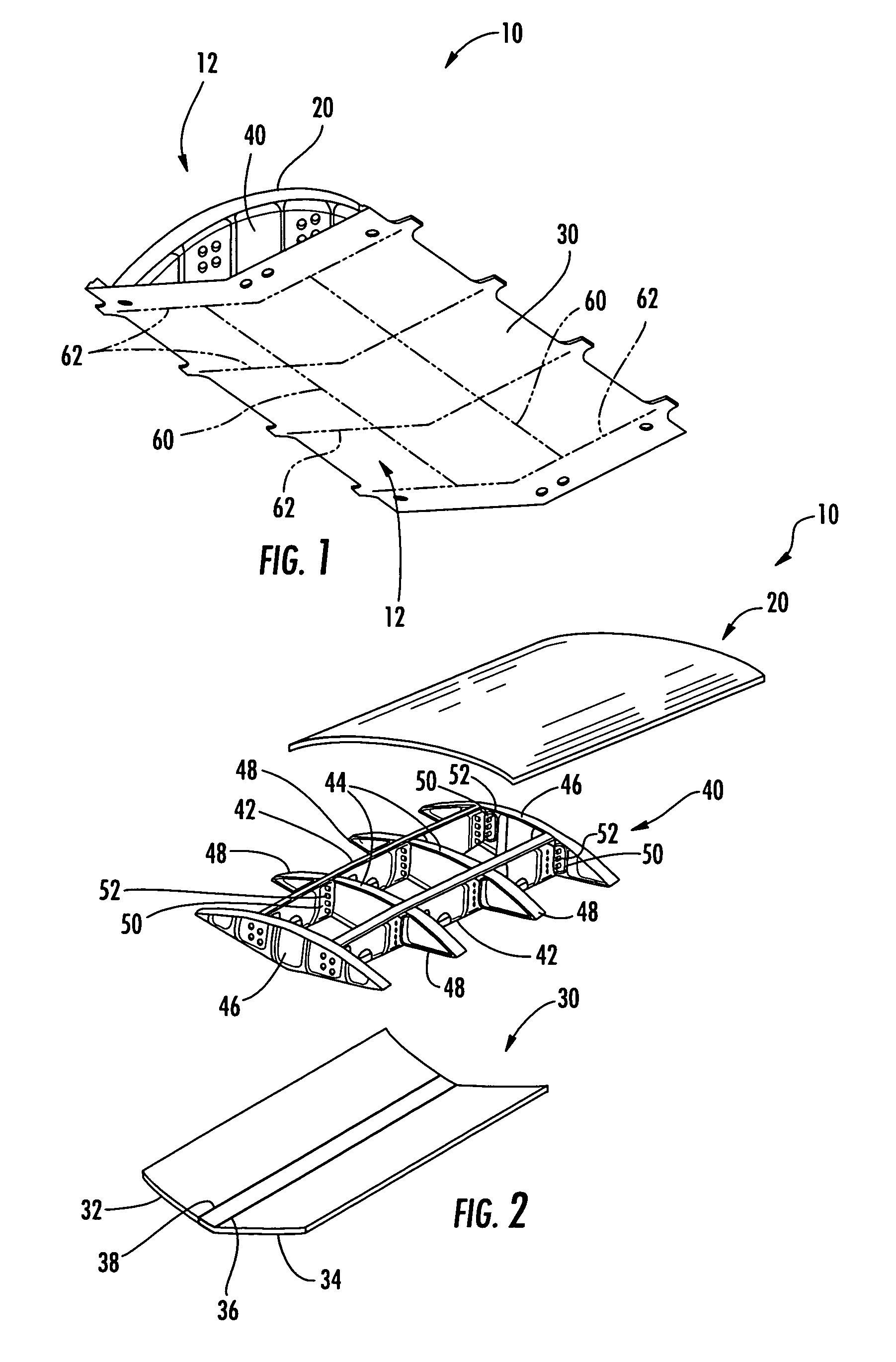
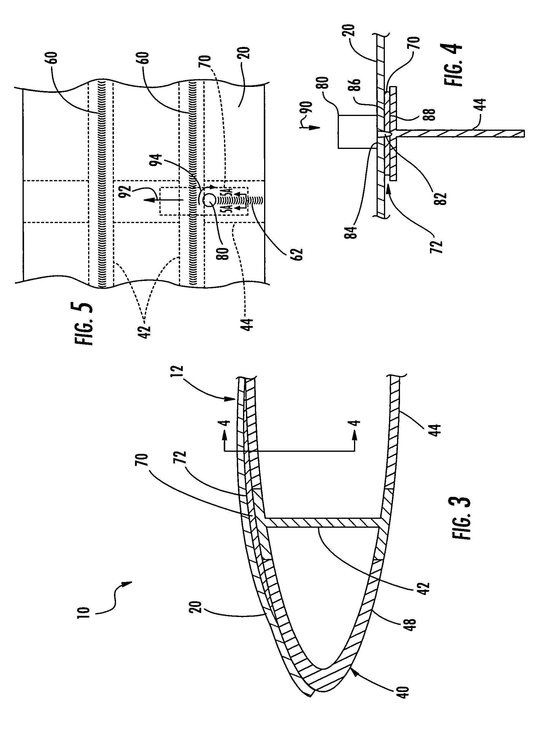
[0023]Referring now to the figures and, in particular, FIG. 1, there is shown a structural assembly 10 according to one embodiment of the present invention. As illustrated in FIG. 1, the structural assembly 10 is an aerospace structural assembly and, more particularly, an airfoil that defines a contoured outer surface 12 such that the assembly 10 is adapted for use as a wing of an aircraft. The structural assemblies according to other embodiments of the present invention can be otherwise configured, and the assemb...


PUM

PropertyMeasurementUnit
angleaaaaaaaaaa
thicknessaaaaaaaaaa
widthaaaaaaaaaa

Abstract

A method of friction stir welding joints with shims and an associated structural assembly is provided. The structural assembly includes one or more skin members that are disposed and friction stir welded to a substructure. A shim is disposed in a space defined by the other members of the assembly, e.g., between adjacent skin members or between a skin member and the substructure. The shim can be friction stir welded to the other members. That is, the adjacent skin members can be connected via the shim, and / or the skin members can be connected to the substructure via the shim. In some cases, the skin members and the substructure are relatively stiff, and the shim substantially fills the space to reduce flexing of the members during the friction stir welding operation.

Description

BACKGROUND OF THE INVENTION[0001]1) Field of the Invention[0002]The present invention relates to the joining of structural members and, more particularly, relates to friction stir welding of joints including at least one shim disposed between structural members.[0003]2) Description of Related Art[0004]Aerospace structural assemblies, such as wings for aircraft, typically include outer flexible sheets, or skins, that are supported in a desired contour to define the outer surface of the structure. According to one conventional method of manufacturing such structures, a number of stringers are connected to the skins to stiffen the skins and facilitate connection of the skins to an underlying support framework of the structure. The stringers, which are typically long angles, channels, or other types of beams, can be connected to the skins by riveting or welding while the skins are supported in a generally flat configuration. Thereafter, the stringers and the skins can be adjusted to the...

Claims


Application Information

Patent Timeline
Patent Type & Authority Patents(United States)
IPC IPC(8): B23K20/12
CPCB23K20/1225B23K20/128B23K20/122
Inventor TALWAR, RAJESHOGONOWSKI, JAMES M.MARTIN, RICKY L.
Owner THE BOEING CO
Why Eureka
Try Eureka