
Universal structural joint for automotive frames

a technology for automotive frames and joints, applied in the direction of roofs, transportation and packaging, vehicle arrangements, etc., can solve the problems of forming joints between respective frame members, affecting the load carrying capacity of the frame, and adding significant cost and weight to the vehicle, so as to achieve the effect of increasing the load carrying capacity

Active Publication Date: 2009-02-10
FORD GLOBAL TECH LLC
View PDF11 Cites 40 Cited by
  • Summary
  • Abstract
  • Description
  • Claims
  • Application Information

AI Technical Summary

Benefits of technology

The invention provides a structural joint configuration for an automotive frame that increases load carrying capabilities. The frame members are bent into an angular orientation and joined together to form a joint in which loads imposed on any frame member are shared with other frame members. The joint can be formed in multiple leg configurations and can withstand high loads by transferring the load from one member to another. The frame members can be formed with any cross-sectional shape and from any conventional material or combination of materials. The joint is durable, inexpensive, carefree of maintenance, facile in assemblage, and simple and effective in use.

Problems solved by technology

The newer, more demanding Federal requirements force countermeasures, i.e. changes to the structure of vehicle frames, which can ultimately add significant cost and weight to the vehicle.
One of the challenges in maintaining frame integrity to withstand the crush loads imposed on the roof structure is the formation of the joints between respective frame members.
If the joints separate during crush loading, the frame will undergo collapse before the respective frame members are crushed.

Method used


Image

  • Universal structural joint for automotive frames
  • Universal structural joint for automotive frames
  • Universal structural joint for automotive frames

Examples


Embodiment Construction

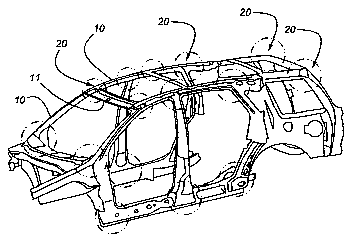
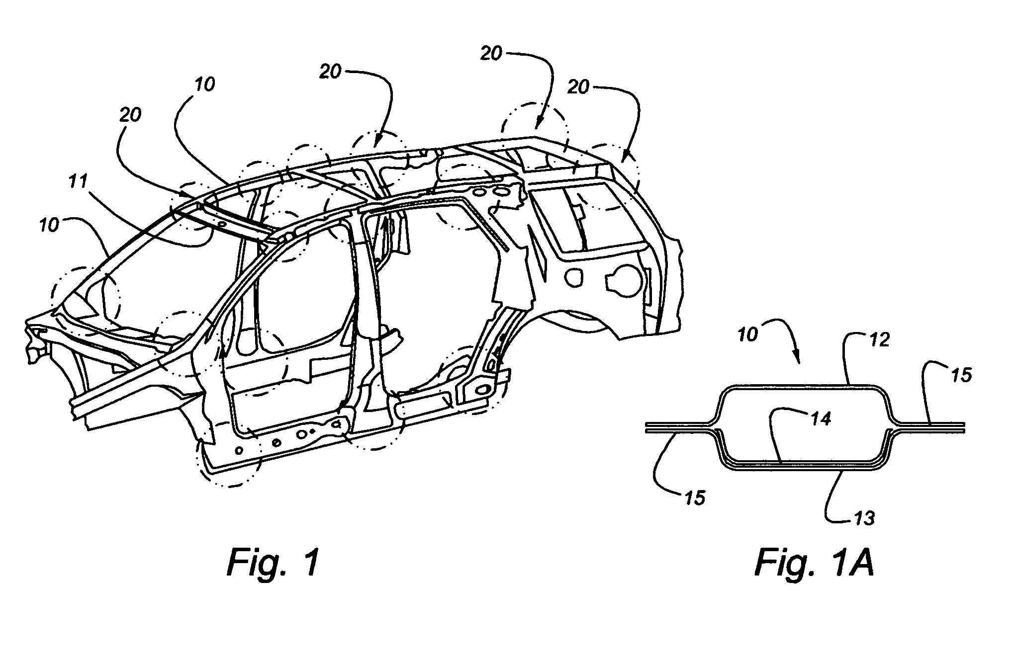
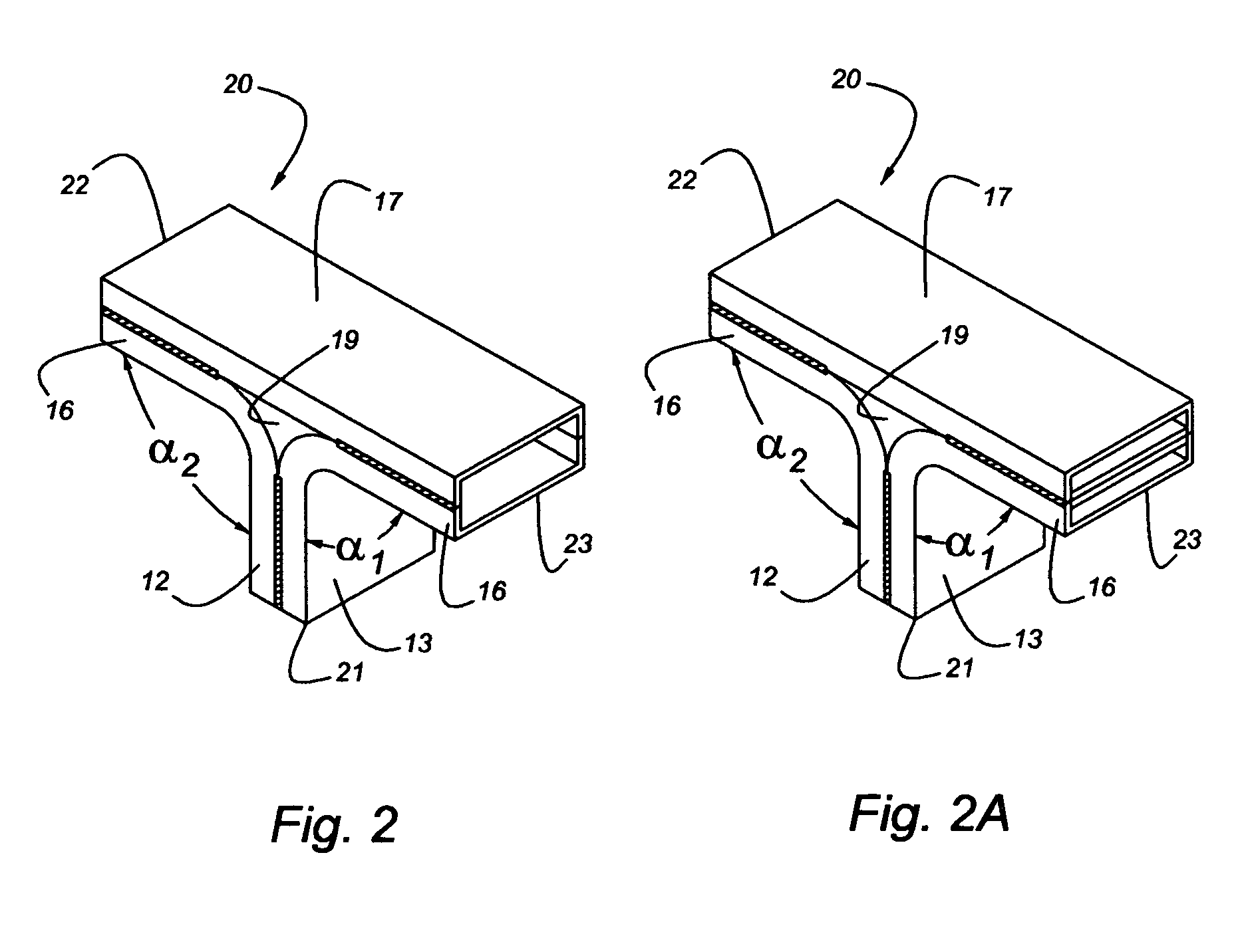
[0032]Referring to FIGS. 1-5, a structural frame configuration for an automotive vehicle incorporating the principles of the instant invention can best be seen. Automotive frame members 10 are typically formed from a pair of shaped members 12, 13, often hat-shaped members, such as is shown in FIG. 1A, that have transversely opposed flanges 15. To beef up the frame member 10, the frame member 10 can be provided with an internal reinforcement member 14, which is typically welded to one of the members 13. The two shaped members 12, 13 can be manufactured in many different forms, including in the way of examples, hat sections, as shown in FIG. 1A; C-shaped sections, as shown in FIG. 2; rectangular cell or tubular member, as shown in FIG. 2A; half-hexagon; half-circle; arched shape; or any combination of such cross-sectional geometry known to one of ordinary skill in the art. These shaped members 12, 13 can be manufactured from any standard material including, in the way of examples, ste...


PUM


Abstract

A structural joint configuration is formed in an automotive frame in which the frame members are bent into an angular orientation and joined together to form a structural joint in the automotive frame in which loads imposed on any of the frame members forming the joint will be transferred to and shared with the other frame members in the joint. The structural joint can be configured with as many legs as needed to conform to the number of frame members entering the joint. The frame members can be formed with any cross-sectional shape and from any conventional material or combination of materials. Joining the frame members at the structural joint can be accomplished by welding or by applying adhesives. Load distribution through the frame members forming the structural joint enables the joint to withstand an application of high loads without major cracks or bending at the structural joint.

Description

FIELD OF THE INVENTION[0001]This invention relates generally to an automotive frame member and, more particularly, to a joint configuration for improving performance under crush loading.BACKGROUND OF THE INVENTION[0002]Federal safety requirements require vehicles to withstand loads on the vehicle roof area for occupant safety and protection. These load requirements, expressed as a percentage of vehicle weight, increase as newer Federal requirements are established. The roof load requirements are intended to simulate loads on the vehicle encountered during a vehicle rollover event. The newer, more demanding Federal requirements force countermeasures, i.e. changes to the structure of vehicle frames, which can ultimately add significant cost and weight to the vehicle. It is essential to minimize the weight of the vehicle, and thus the countermeasures adopted to meet the newer Federal safety requirements, as added weight to the vehicle frame translates into increased load requirements a...

Claims


Application Information

Patent Timeline
Patent Type & Authority Patents(United States)
IPC IPC(8): B60J7/00
CPCB62D25/04B62D25/06B62D27/023
Inventor BELWAFA, JAMELFILETA, BAHIGNUSIER, SAIEDMAHMOOD, HIKMAT
Owner FORD GLOBAL TECH LLC
Learn More