
Gas micro burner

a micro-burner and micro-gas technology, which is applied in the direction of burners, combustion types, burner material specifications, etc., can solve the problems of increasing the overall length of the burner apparatus, affecting the flow rate of fuel, and affecting the efficiency of the burner, so as to achieve the effect of low fuel mass flow rate requirements

Inactive Publication Date: 2009-02-10
R J REYNOLDS TOBACCO COMPANY
View PDF45 Cites 71 Cited by
  • Summary
  • Abstract
  • Description
  • Claims
  • Application Information

AI Technical Summary

Benefits of technology

The burner generates a stable, pre-mixed flame with significantly lower fuel flow rates than conventional burners, allowing for a smaller size and wider application scope, including integral cigarette lighters, with reduced soot and unburned hydrocarbons.

Problems solved by technology

Unfortunately, diffusion flame burners tend to produce soot from unburned hydrocarbons and pyrrolitic products that occur due to incomplete combustion of the gaseous fuel.
Furthermore, flames produced by diffusion burners tend to be unstable and bend as the burner is rotated.
However, the presence of an effective venturi tends to add to the overall length of the burner apparatus.
In addition, the fuel mass flow rate requirement of the burner affects the overall size of the combination of the burner and fuel storage container.

Method used


Image

  • Gas micro burner
  • Gas micro burner
  • Gas micro burner

Examples


Embodiment Construction

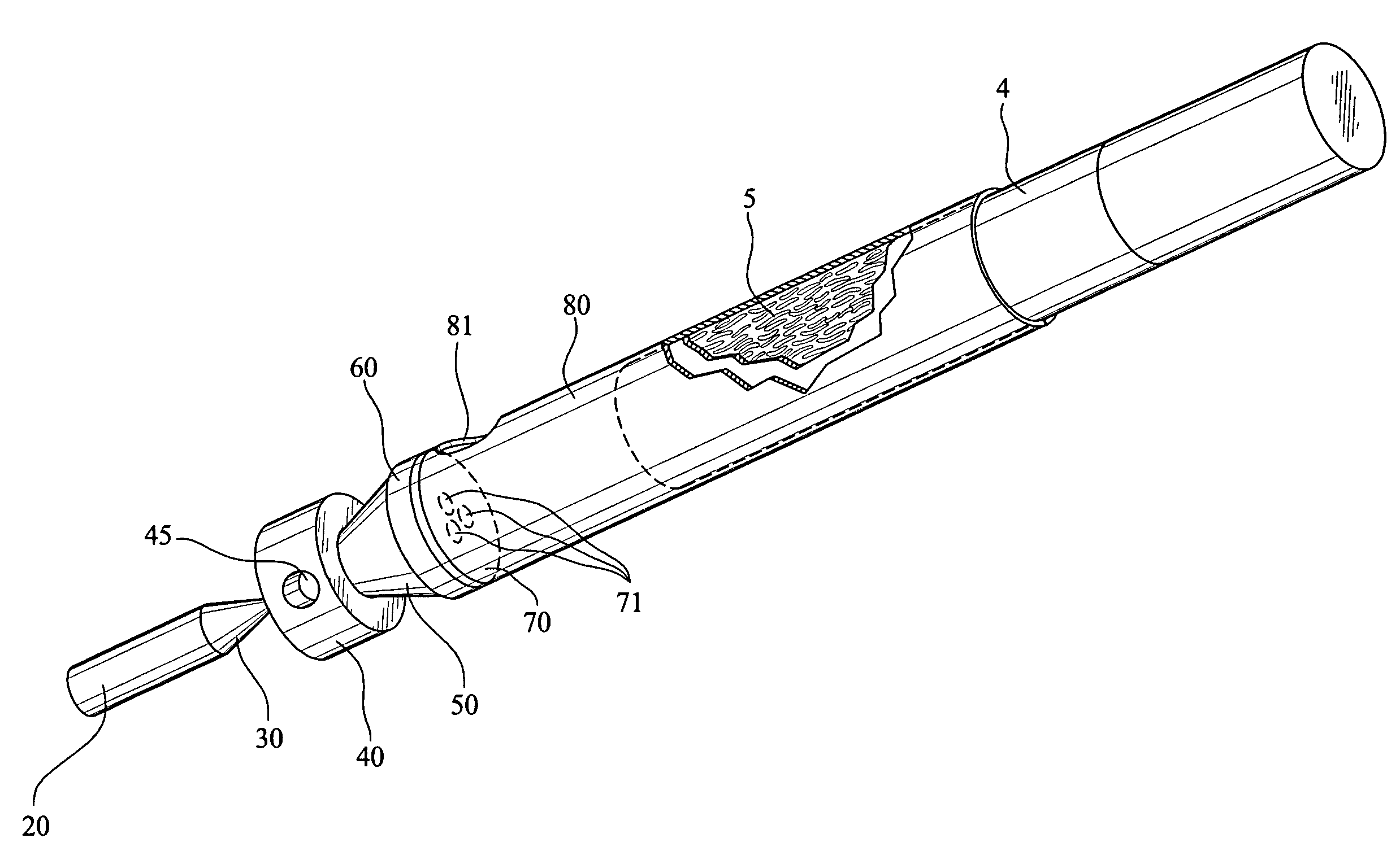
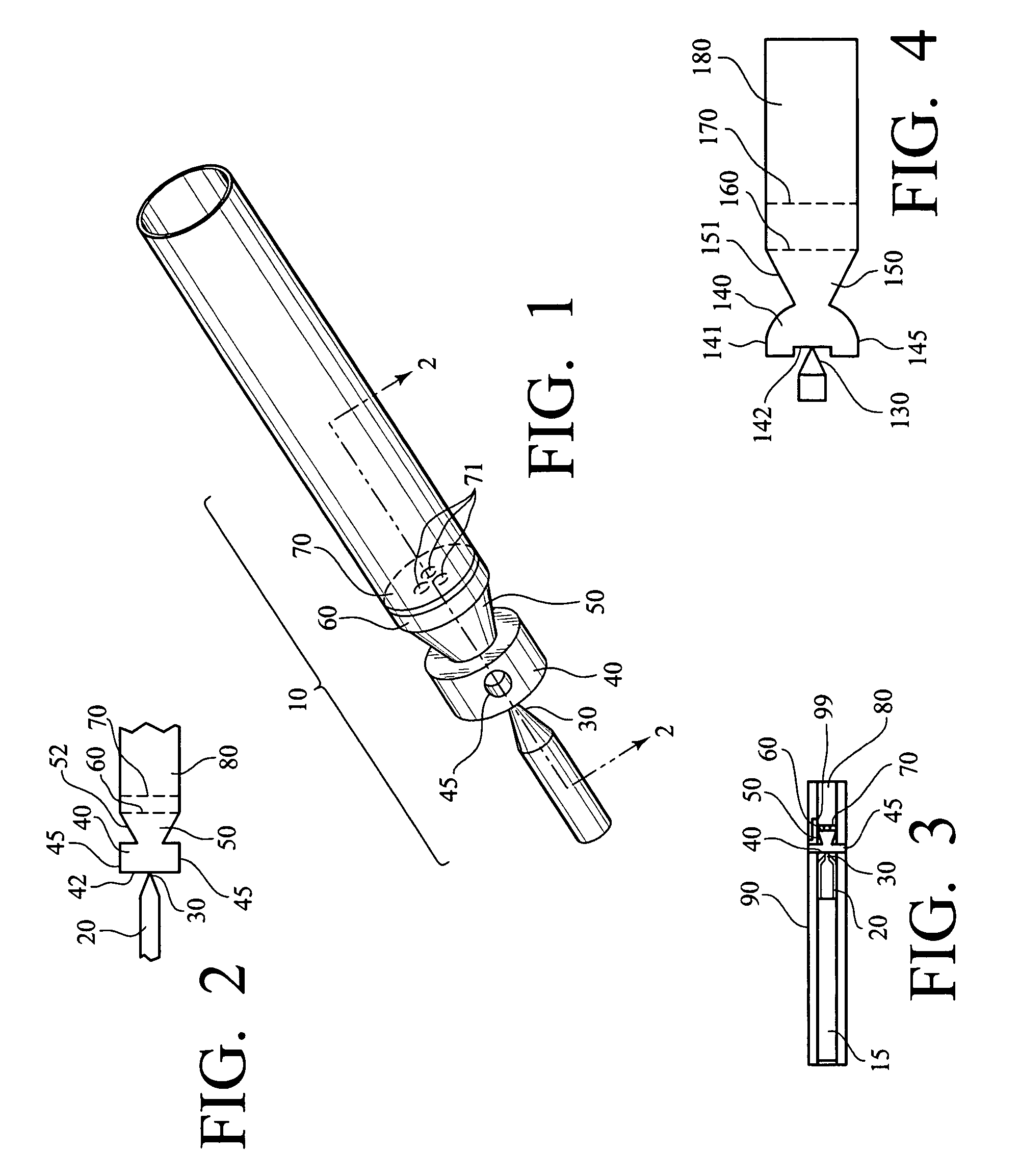
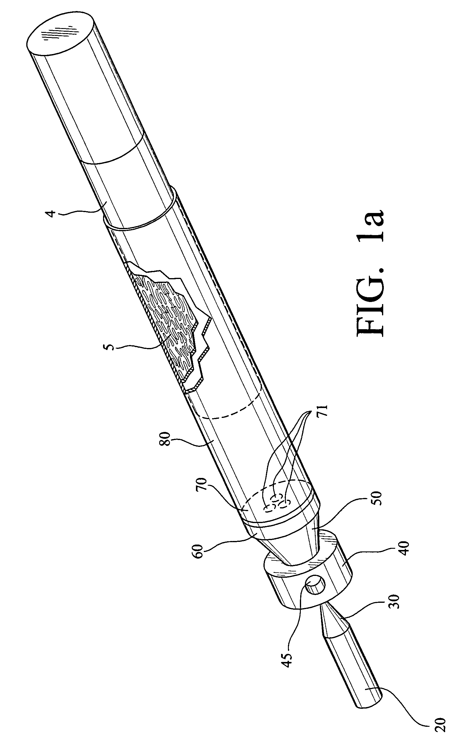
[0050]As shown in the figures, a gas burner 10 includes a fuel inlet 20, a venturi, which includes a nozzle 30 and an oxygenation chamber 40 with at least one air inlet 45, a mixing chamber 50, at least one permeable barrier or mixing screen 60 and a flame holder 70. The gas burner 10 produces a stable pre-mixed flame that is generated with lower fuel mass flow rates than conventional burners. As a result, a lighter employing the gas burner 10 of the present invention may be sized smaller than conventional commercial gas lighters.

[0051]FIG. 1 shows the gas burner 10 of the present invention. The fuel inlet 20 connects a fuel storage container 15, as shown in FIG. 3, with the nozzle 30. The fuel inlet 20 provides a pathway through which gaseous fuel may be fed from the storage container 15, in which it is contained, to the gas burner 10. The fuel may be any gaseous fuel known in the art, including low molecular weight hydrocarbons such as methane, ethane, propane, butane, and acetyle...


PUM


Abstract

A micro gas burner is provided that generates a stable, pre-mixed flame that produces little to no soot or unburned hydrocarbons. The gas burner includes a fuel inlet, nozzle, oxygenation chamber with at least one air inlet, a mixing chamber having a frustoconical inner wall, at least one permeable barrier and a flame holder. The gas burner thoroughly mixes fuel and entrained air to form a nearly stoichiometric mixture prior to combustion. The gas burner mixes the fuel and air so thoroughly that it requires a lower fuel flow rate than would otherwise be necessary to produce a stable, pre-mixed flame. The gas burner may include an optional flame tube with an optional exhaust port in which a flame is contained and sequestered from diffusing air.

Description

CROSS-REFERENCE TO RELATED APPLICATIONS[0001]This continuation-in-part application claims priority to and benefit from currently pending U.S. application Ser. No. 10 / 217,695, filed Oct. 25, 2002, which is incorporated herein by reference.STATEMENT REGARDING FEDERALLY SPONSORED RESEARCH OR DEVELOPMENT[0002]Not applicable.REFERENCE TO A “SEQUENTIAL LISTING,” A TABLE, OR A COMPUTER PROGRAM LISTING APPENDIX SUBMITTED ON A COMPACT DISC[0003]Not applicable.1. FIELD OF THE INVENTION[0004]This invention relates generally to gas combustion burners. More particularly, the present invention relates to an integral gas burner for a smoking article employing combustion of a pre-mixed gaseous fuel.2. DESCRIPTION OF THE RELATED ART[0005]Small scale gas combustion burners, such as those used in cigarette lighters, are well known in the art. Most cigarette lighters use buoyancy to entrain air for diffusion combustion. The fuel vapors and air meet at the point of ignition and burn instantaneously. Hen...

Claims


Application Information

Patent Timeline
Patent Type & Authority Patents(United States)
IPC IPC(8): F23D14/62F23D14/14F23D14/10F23Q2/16
CPCF23D14/105F23D14/14F23Q2/163F23D2203/1012F23D2203/1055F23D2203/106F23D2212/10F23D2212/201F23Q2/32
Inventor ST. CHARLES, FRANK KELLEYADIGA, KAYYANI C.
Owner R J REYNOLDS TOBACCO COMPANY
Learn More