
Device for ligating an anatomical structure

a technology of anatomical structure and ligation device, which is applied in the direction of staples, nails, medical science, etc., can solve the problems of inability to use the fingers or the hands, requiring complex equipment, and sometimes of inappropriate size,

Active Publication Date: 2009-02-10
SOFRADIM PROD SAS
View PDF12 Cites 65 Cited by
  • Summary
  • Abstract
  • Description
  • Claims
  • Application Information

AI Technical Summary

Benefits of technology

[0009]An object of the invention is to mitigate this lack. Individual devices for use once only can be suitable, because two clips can suffice for treating simple lesions, an appendectomy, or an isolated blood vessel ligature.
[0018]a slide making it possible to act on the means for moving the second branch away from or towards the first branch.
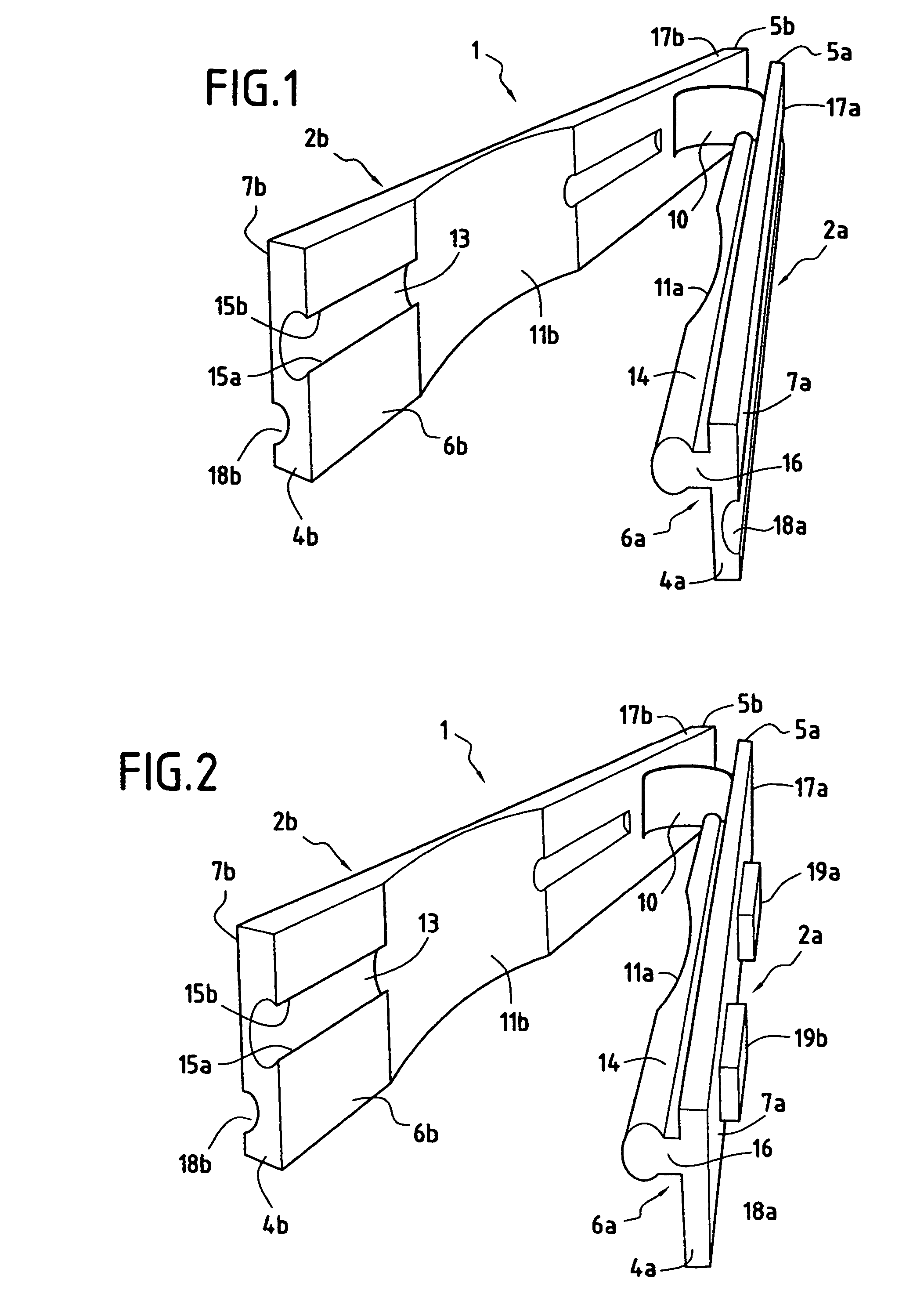
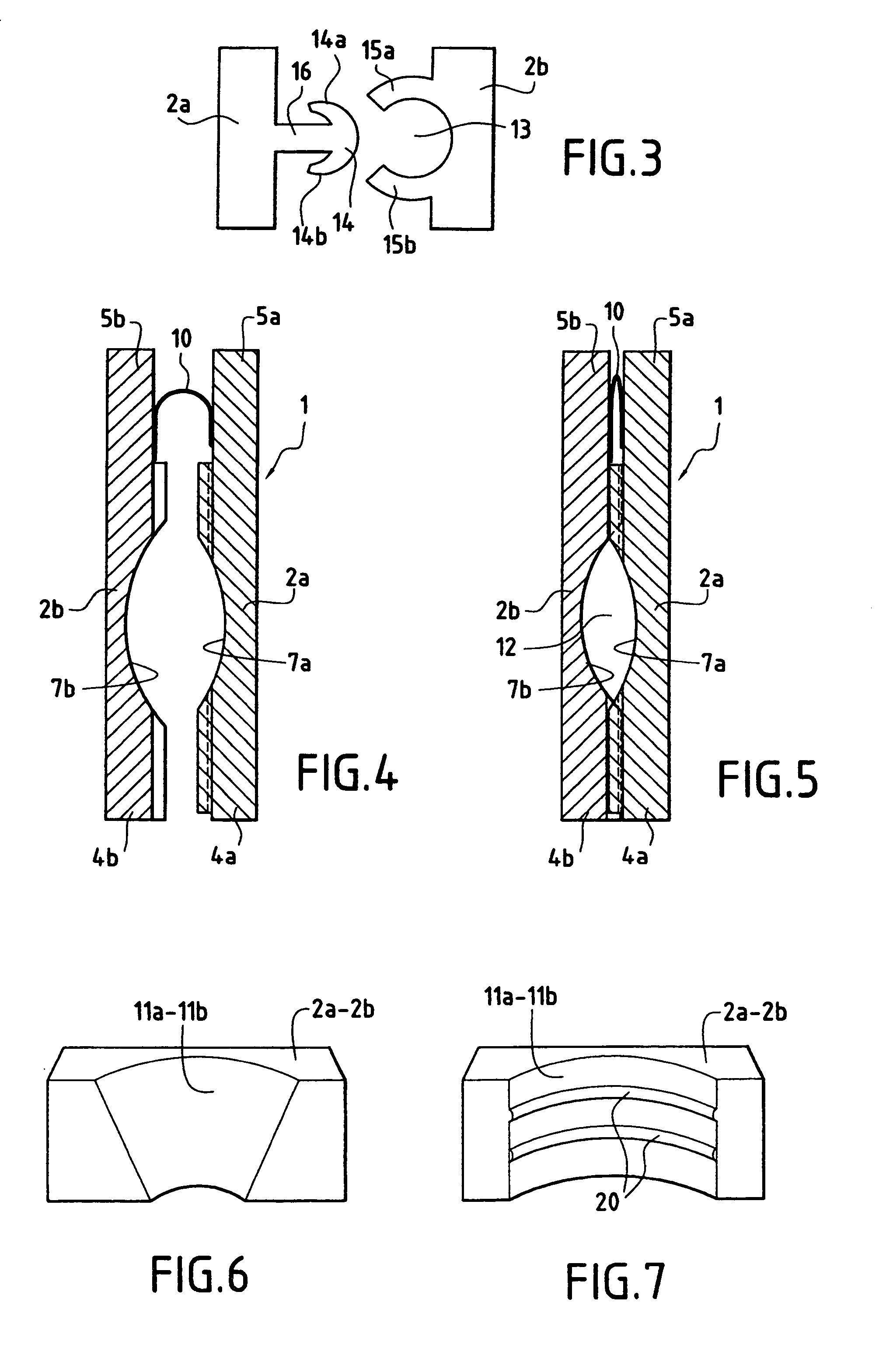
[0023]With this first embodiment of the ligature element, the slide is in the form of a trough having two parallel axial lips, said lips having, at one end, a pair of facing projections designed to slide in longitudinal guide groves provided in the outside face of at least one of the two branches of said ligature element and in the outside face of the side wall of the holder, the outside faces of said branches having, in said guide grooves, at least one pair of protuberances which, by co-operating with the pair of projections of said slide, while said slide is moving axially, cause the two branches of said ligature element to clamp together and cause the fastening means to snap-fasten together.
[0027]The holder is then further provided with a leaf spring or spring blade connected to the distal end of the side wall of said holder via a flexible hoop, said spring blade having a convex surface facing said side wall, which convex surface is in abutment against the outside face of the second branch of said ligature element, and the slide is constituted by a ring through which said side wall and said spring blade pass, axial movement of said ring along said side wall causing said spring blade to move towards or away from said side wall.
[0035]a wire guide or feedthrough passing through said keeper and, at the front of the distal end of said keeper, forming an eye into which the distal end of the ligature element is inserted when the spring blade forms a circle, so that traction exerted on said feedthrough causes said eye to be hooked by the barb, causes the distal portion of the ligature element to be inserted into said keeper, and causes said ligature element to be tightened.

Problems solved by technology

That minimally-invasive technique involving the use of fine, cylindrical instruments passed through the abdominal wall without using a large opening makes it impossible to use the fingers or the hand.
The celioscopic technique also involves these operating stages, but it represents a more difficult technique.
As for using metal clips, that requires equipment that is complex, costly, and sometimes of inappropriate size.
Ligating the appendicular base, which, in theory, is relatively easy, is often more difficult than expected.
Admittedly, the result is satisfactory but such instruments cannot be used systematically because they require accesses that are larger than those usually formed for surgical resection of the appendix, and they are costly.
Currently, no other equipment exists for performing the various surgical stages.

Method used


Image

  • Device for ligating an anatomical structure
  • Device for ligating an anatomical structure
  • Device for ligating an anatomical structure

Examples


second embodiment

[0107]FIG. 18 shows a ligature element 61 which has a first branch 62a that is semi-rigid and a second branch 62b that is also semi-rigid, each branch having a proximal end 64a, 64b, a distal end 65a, 65b, an inside face 66a, 66b and an outside face 67a, 67b. A flexible thin strip 70 interconnects the distal ends 65a, 65b of the two branches 62a and 62b. Said ligature element 61 is also preferably made by molding a suitable material, complying with medical requirements, in one piece or in a plurality of assemblable pieces.

[0108]On its inside face 66a, and in the immediate vicinity of its proximal end 64a, the first branch 62a has a keeper 71 of substantially rectangular cross-section, having a wall 72 remote from the inside face 66a.

[0109]On the outside face 67b of its proximal end, the second branch 62b has a plurality of transverse serrations 73. The cross-section of the duct 74 through the keeper 72 is determined such that the proximal portion of the second branch, inserted via ...

third embodiment

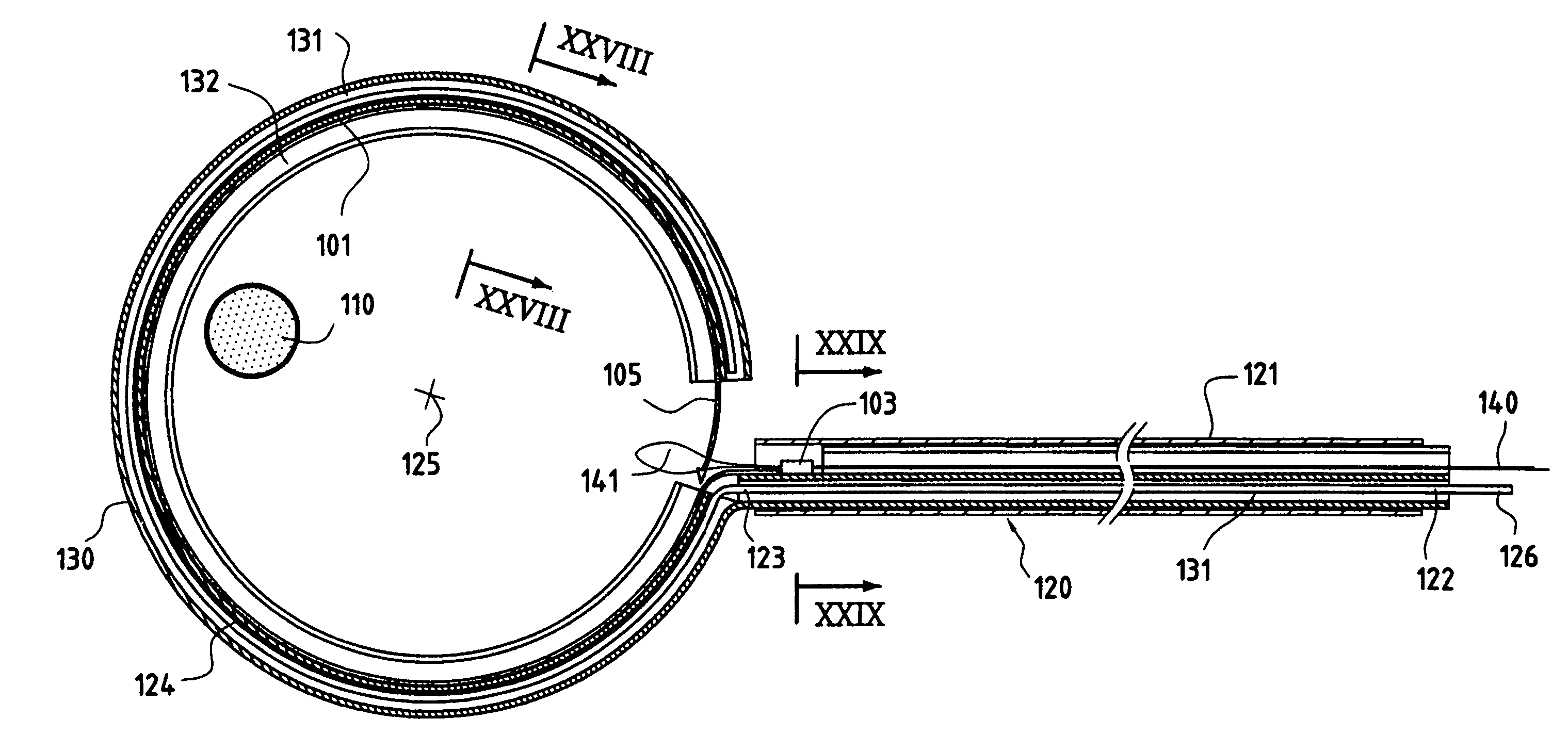
[0127]FIGS. 23 and 24 show a ligature element 101 which is in the form of a flexible, relatively long, strip whose proximal end 102 has a keeper 103 on its top or inside face, and whose end of its distal portion 104 has a barb 105 on its top or inside face. The barb 105 serves to be inserted by traction into the keeper 103 via the distal end 106 thereof. By continuing to pull on the barb 105, the distal end 104 is caused to penetrate into and to slide in the keeper 103, and the portion of the strip adjacent to the keeper 103 forms a loop for tightening around the anatomical element to be ligated, it then being possible for the distal portion 104 then to be cut off in front of the proximal end 107 of the keeper 103. The bottom face of the ligature element 101 can, in its middle portion, have serrations that enable it to be locked in the keeper 103 after tightening.

[0128]FIGS. 25 to 30 show the applicator 120 used for putting in place the ligature element 101 around an anatomical elem...


PUM


Abstract

A device for ligating an oblong anatomical structure having a ligature element. A proximal portion of the ligature element may have a keeper and the distal portion may have a barb which is slidably received in the keeper. The device may further include an applicator for putting the ligature element in place, a rectilinear metal rod which extends in the tube and which, at its distal end has a spring blade, and a sheath having a radial outer duct in which the spring blade is received, and a radial inner guide groove in which the ligature element is received.

Description

[0001]This is a 371 national phase application of PCT / FR04 / 00403 filed 23 Feb. 2004, claiming priority to French Patent Application No. 0302216 filed 24 Feb. 2003, the contents of which are incorporated herein by reference.BACKGROUND OF THE INVENTION[0002]The invention relates to a device for ligating an anatomical structure.[0003]The device of the invention relates to the field of surgical equipment making it possible to perform surgery, in particular in small spaces, especially under celioscopy. That minimally-invasive technique involving the use of fine, cylindrical instruments passed through the abdominal wall without using a large opening makes it impossible to use the fingers or the hand.[0004]For example, for surgical resection of the vermiform (or cecal) appendix, the operation is relatively simple when it is performed via conventional open surgery; it is necessary to control and then cut the vessels that supply the appendix and that are included in an anatomical fold known ...

Claims


Application Information

Patent Timeline
IPC IPC(8): A61B17/04A61B17/12A61B17/00A61B17/064A61B17/122A61B17/128
CPCA61B17/12013A61B17/122A61B17/1285A61B17/0643A61B2017/00004
Inventor SGRO, JEAN-CLAUDE
Owner SOFRADIM PROD SAS
Learn More