
Method and assembly for determining and/or producing a drive or parts for a drive and interface and method for determining an operational reliability factor SB

a technology of operational reliability factor and drive, which is applied in the direction of program control, total factory control, structural/machine measurement, etc., can solve the problem that the method may require only a small amount of computing tim

Inactive Publication Date: 2010-11-02
SEW-EURODRIVE GMBH & CO KG
View PDF5 Cites 2 Cited by
  • Summary
  • Abstract
  • Description
  • Claims
  • Application Information

AI Technical Summary

Benefits of technology

[0008]In this context, the lack of design definition in the case of geared motors, primarily in extreme ranges of the standard applications and in servo technology, may be markedly reduced, taking into consideration the overload capability of gear-unit elements, in the endurance-limit range. For this purpose, four-dimensional load collectives may be considered, with whose aid one also attains, inter alia, a precise knowledge of the load from the start-up dynamics. A method characteristic is the consideration of strength in a component-individual manner instead of a general representation of the geared motor as a “black box.” Am aspect is, moreover, that the load capacity of the output-shaft components, stressed by lateral forces, is a function of the partial collective and therefore a function of the load. In addition, not only lateral force, e.g., its amount and direction, but also the axial force may be taken into account. Moreover, the method may require only a small amount of computing time and may be easily configurable for the operator. An aspect is also that a quantitative variable, namely, operational reliability factor SB, is determined, and therefore a quantitative evaluation of each drive of the entire production series is usable based on the application or the application data. If the application data change, this quantitative value also changes. Thus, the optimal drive may be determinable individually for each application.
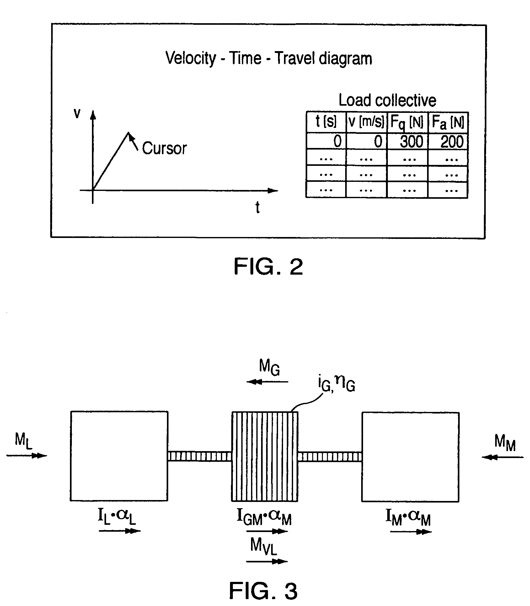
[0010]In an example embodiment, the load collective may be at least four-dimensional and may include at least information about the time characteristic of the variables torque, speed, axial force and lateral force. In particular, direction and amount or, alternatively, two corresponding components are possible when entering the lateral force. In an example embodiment, even the contact point of the lateral force may be input. This may provide that it is possible to input not only steady-state loads having constant values, but also time characteristics of the real application. In addition, not any imaginary maximum value for the variables, e.g., for the load collective, is used, but rather the effective variable values occurring in the specific partial collective of the load collective. Moreover, even the direction and the amount of the lateral force and / or even the contact point of the lateral force on the specific shaft section may be considered. This may permit a precise determination of the operational reliability factor, even as a function of the lateral-force direction and its contact point. The drive to be produced may be determined far more accurately precisely because a separate value is able to be taken into account for each partial collective. Therefore, e.g., smaller and / or more cost-effective drives may be determined, manufactured and used. In addition, reliability may be markedly increased.
[0013]In an example embodiment, the load collective includes partial collectives which are produced by classification, the respective classes including specific value ranges of associated variables. This may provide that the quantity of data belonging to time characteristics may be reduced.
[0016]In an example embodiment, the critical-load characteristic curve is able to be parameterized by two parameters in a lateral force / torque diagram and / or the critical-load characteristic curve is able to be parameterized by four or five parameters in a lateral force / axial force diagram. A few parameters may be sufficient to describe the critical-load characteristic curve with sufficient accuracy. Therefore, the computing time may be considerably reduced. In particular, even closed solutions—which works only for a particular company's product—for the cutting of curves may be indicated, which may greatly reduce the computing time and may further simplify the method.
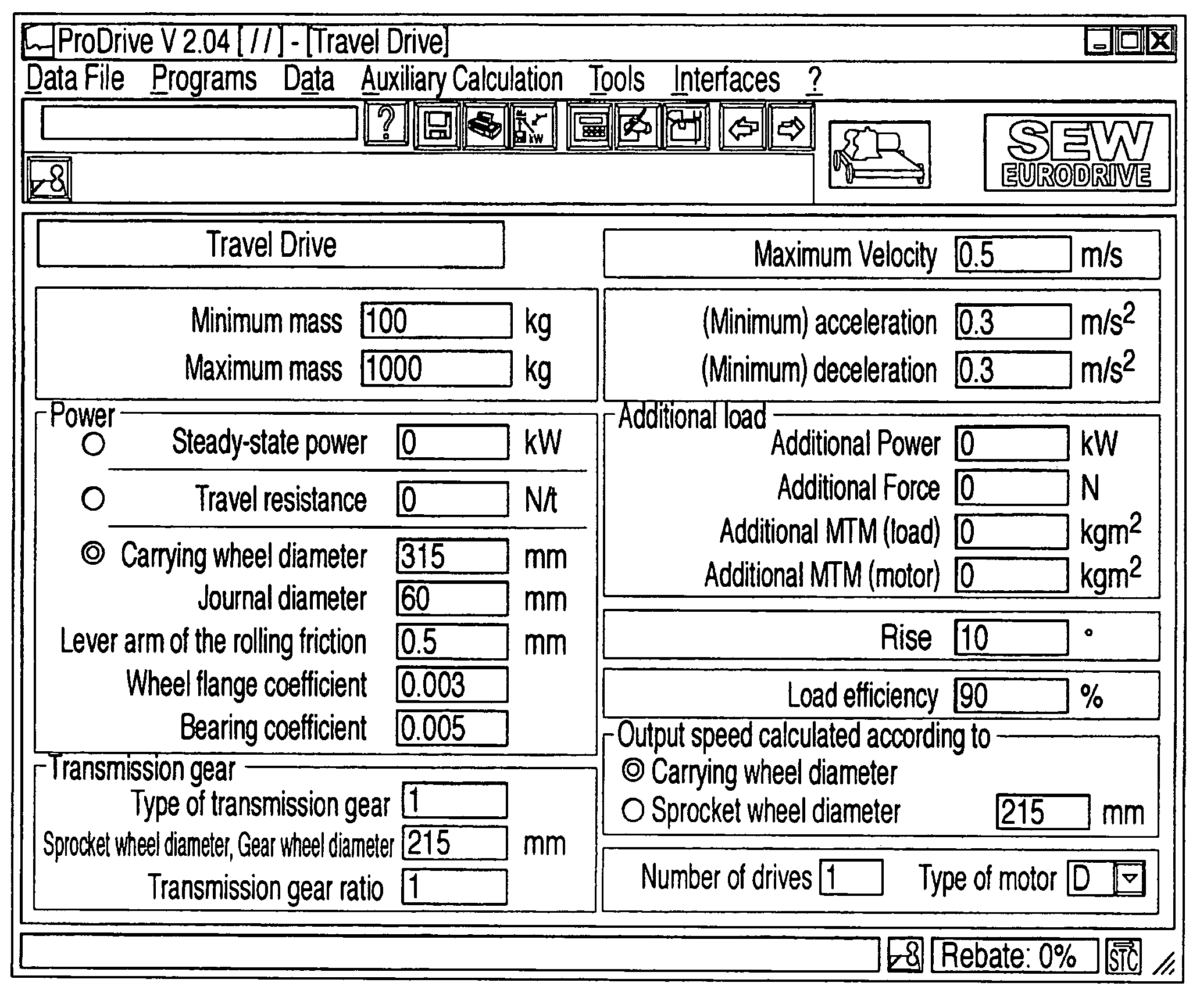
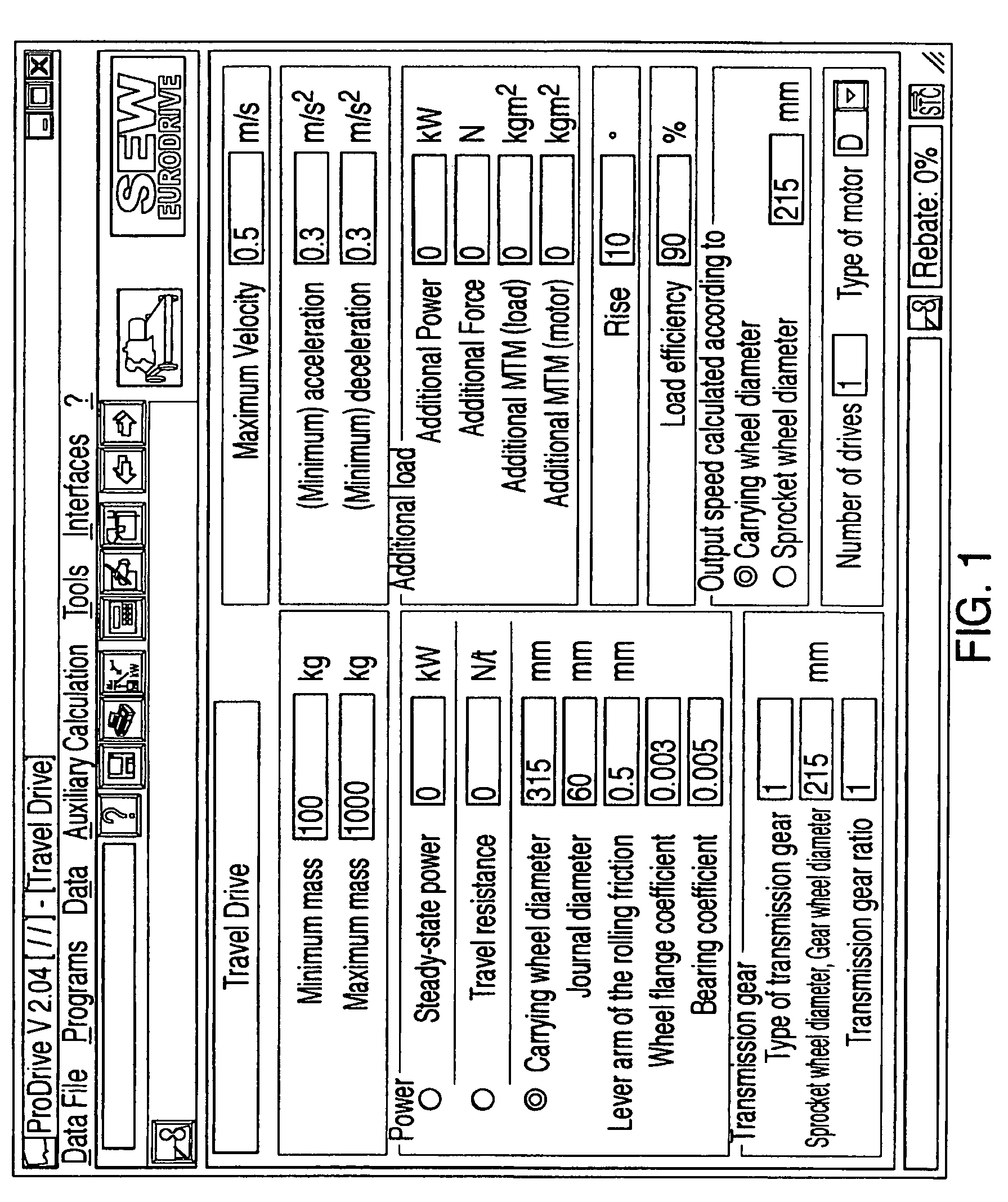
[0024]Features with respect to the interface for the input and output of data when working with a method as discussed herein are that the interface includes a graphic user interface and / or a data interface for the input and output of data, it being possible to input load-alternation numbers or travel diagrams. Thus, any man / machine interface having device(s) for graphic display is also usable, e.g., a computer with screen, keyboard and mouse. Since the application data include extensive quantities of data, e.g., the time characteristics, the application data are able to be input quickly and easily with low susceptibility to error using the graphic input possibility.
[0031]In an example embodiment, the data is able to be input on a first computer that is connectible via Internet and / or other networks, e.g., Intranet, to at least one further computer, the further computer being usable for implementing the method, e.g., also for the placing of orders and the tie-in of the manufacturing facilities. This may provide that the method is not carried out on the first computer. Thus, the customer inputs the customer's application data, e.g., in graphic manner, on the customer's computer using the customer's Internet browser, and then receives a suggestion for the optimal drive from the further computer connected via Internet. The customer may thus need no installation of a program on the customer's computer, may avoid problems associated with that, and may always be offered the newest version of the program belonging to the method. In addition, the supplier of the program may be protected against software piracy.

Problems solved by technology

Moreover, the method may require only a small amount of computing time and may be easily configurable for the operator.

Method used


Image

  • Method and assembly for determining and/or producing a drive or parts for a drive and interface and method for determining an operational reliability factor SB
  • Method and assembly for determining and/or producing a drive or parts for a drive and interface and method for determining an operational reliability factor SB
  • Method and assembly for determining and/or producing a drive or parts for a drive and interface and method for determining an operational reliability factor SB

Examples


Embodiment Construction

[0042]In an example embodiment of the present invention, the application data of a drive, e.g., of a geared motor, include data concerning the provided masses, velocities, accelerations, decelerations, forces, torques, powers, geometric data, frictional forces, etc. Also belonging to the application data in the case of special applications is information concerning the service life, ambient temperature and / or operating temperature. Desired information concerning the reliability, such as minimum and / or maximum reliability factor, may also be input.

[0043]In an exemplary embodiment of a method and / or a system according to the present invention, a travel diagram and / or application data are first input without information concerning the type of installation or machine.

[0044]In an example embodiment, the type of installation or machine is selected first.

[0045]The typical application data relevant in each instance for this installation or machine may thereupon be entered. In this context, ...


PUM


Abstract

An interface and method for determining an operational reliability factor SB for a drive, including gear unit and motor, provided for a load, an operational reliability factor SB is determined for the drive or its gear unit from a load collective that is at least three-dimensional.

Description

RELATED APPLICATION INFORMATION[0001]This application is a continuation of U.S. patent application Ser. No. 10 / 492,506, filed Apr. 12, 2004 now abandoned, which is a national phase of International Application Serial No. PCT / EP02 / 09581 filed on Aug. 28, 2002, and claims priority to German Patent Application Serial No. 10150034.3 filed on Oct. 11, 2001, the entirety of each of which is incorporated herein by reference thereto.FIELD OF THE INVENTION[0002]The present invention relates to a method and a system for determining and / or producing a drive or parts for a drive, as well as an interface and a method for determining an operational reliability factor SB.BACKGROUND INFORMATION[0003]Manufacturers of drives, including converters, electric motors and gear units, usually offer an extensive production series of drives to the customer, from which the customer is able to select the best possible drive for the customer's special application in accordance with the customer's requirements. ...

Claims


Application Information

Patent Timeline
Patent Type & Authority Patents(United States)
IPC IPC(8): G06F19/00G05B19/418
CPCG05B19/41875G01M99/00G05B2219/32187Y02P90/02
Inventor BARTON, PETERSCHAFER, ROMAN
Owner SEW-EURODRIVE GMBH & CO KG
Learn More