Radiation image pick-up device and method therefor, and radiation image pick-up system

a technology of radiation image and pickup device, which is applied in the direction of television system, radio control device, instruments, etc., can solve the problems of insufficient s/n ratio depending on the photographing mode and little tolerance for differences in attenuation

Inactive Publication Date: 2009-02-10
CANON KK
View PDF18 Cites 30 Cited by
  • Summary
  • Abstract
  • Description
  • Claims
  • Application Information

AI Technical Summary

Benefits of technology

[0012]In light of the foregoing, the present invention has been made in order to solve the above-mentioned problems, and it is therefore an object of the present invention to provide an inexpensive and high-performance radiation image pick-up device and a method therefor, and an inexpensive and high-performance radiation image pick-up system which are capable of freely switching sensitivity over to another one in correspondence to a situation and an object of the image photographing to flexibly cope therewith, i.e., capable of carrying out both still image photographing and moving image photographing for example which are largely different from each other in dosage of exposure to radiation and which are also different in required sensitivity so as to meet that request.
[0029]According to the present invention, there are realized the inexpensive and high-performance radiation image pick-up device and radiation image pick-up system which are capable of freely switching sensitivity over to another one in correspondence to a situation and an object of the image photographing to flexibly cope therewith, i.e., capable of carrying out both still image photographing and moving image photographing for example which are largely different from each other in dosage of exposure to radiation and which are also different in required sensitivity so as to meet that request.

Problems solved by technology

Thus, the S / N ratio may become insufficient depending on the photographing modes.
That is, the conventional radiation image pick-up device involves a problem in that it has little tolerance for differences in the attenuation of the X-rays between different subjects, or for large differences in the dosage of exposure to the X-rays such as when still image photographing and moving image photographing are performed.

Method used


Image

  • Radiation image pick-up device and method therefor, and radiation image pick-up system
  • Radiation image pick-up device and method therefor, and radiation image pick-up system
  • Radiation image pick-up device and method therefor, and radiation image pick-up system

Examples


first embodiment

[0046]First of all, a first embodiment of the present invention will hereinafter be described.

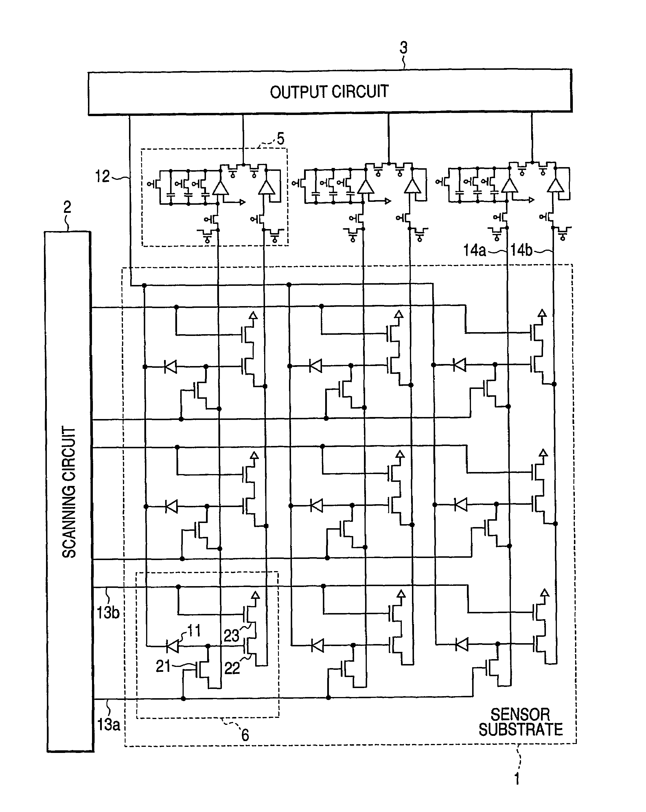
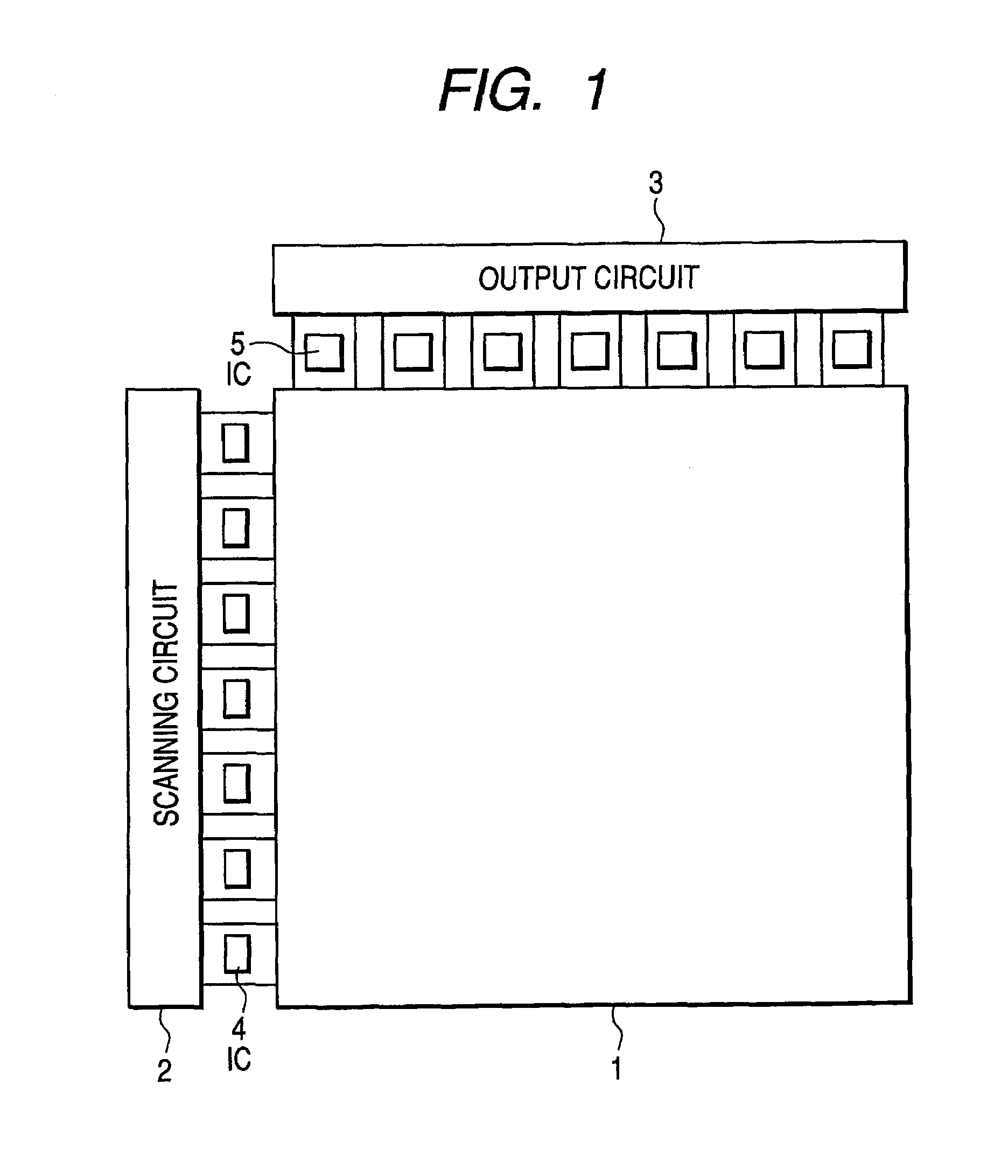
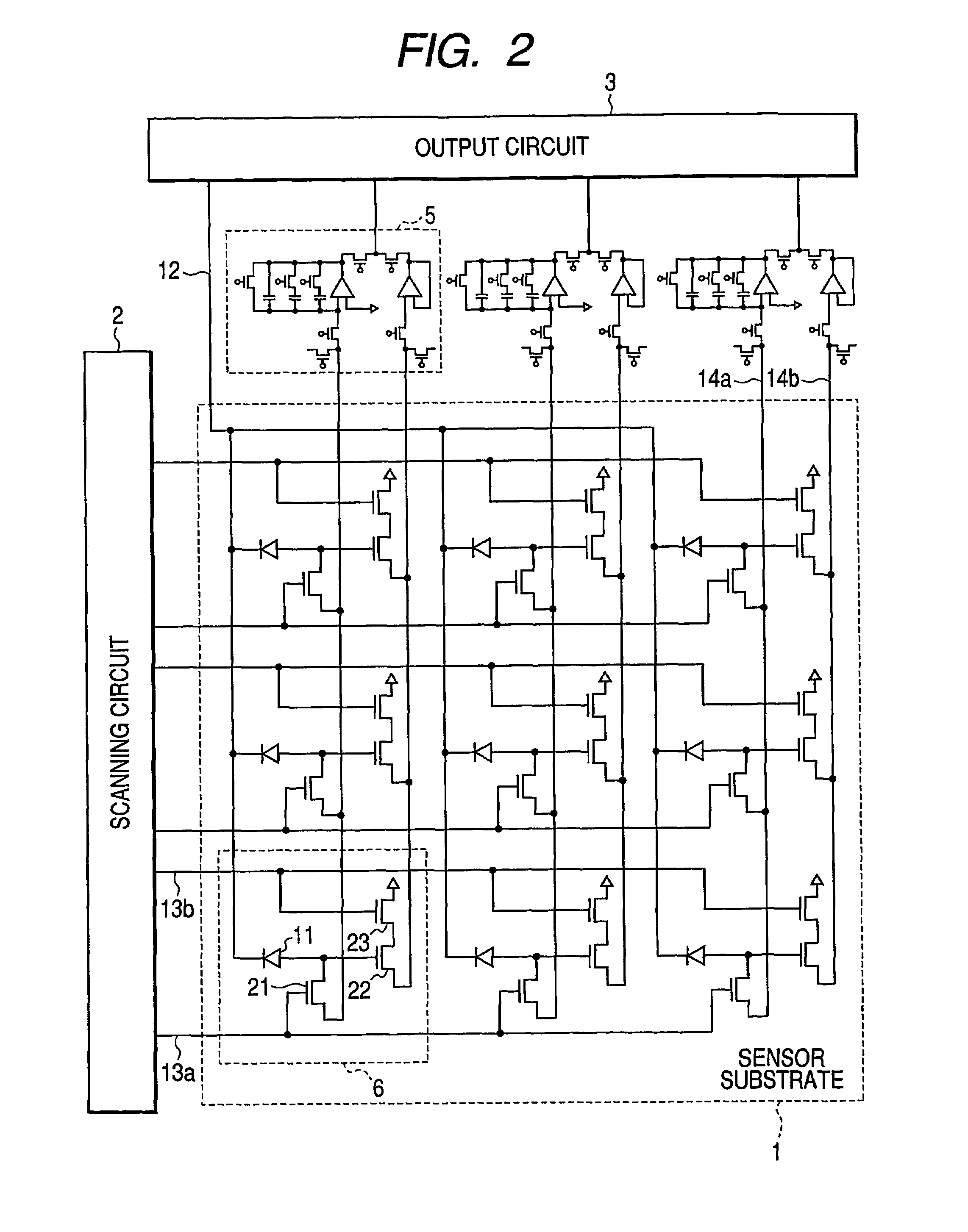
[0047]FIG. 1 is a schematic plan view schematically showing an example of a radiation image pick-up device according to a first embodiment of the present invention, FIG. 2 is a corresponding circuit diagram of the radiation image pick-up device according to the first embodiment of the present invention, and FIG. 3 is an equivalent circuit diagram of one pixel and a signal reading circuit in the radiation image pick-up device according to the first embodiment of the present invention.

[0048]It will be noted that, at the level of detail shown in FIG. 1, the overall structure of this embodiment is like that of the conventional structure shown in FIG. 11. As shown in FIG. 1, the radiation image pick-up device includes a sensor substrate 1 in which a plurality of pixels each having a photoelectric conversion function are disposed, a scanning circuit 2 for scanning the pixels, a signal output circ...

second embodiment

[0077]Next, a radiation image pick-up device according to a second embodiment of the present invention will hereinafter be described.

[0078]The radiation image pick-up device of this embodiment has nearly the same configuration as that of the radiation image pick-up device of the first embodiment but is different in that ICs of the signal output circuit is slightly different in configuration from those of the signal output circuit of the first embodiment.

[0079]FIG. 6 is an equivalent circuit diagram of the radiation image pick-up device according to the second embodiment of the present invention, and FIG. 7 is an equivalent circuit diagram of one pixel and the signal reading circuit in this radiation image pick-up device. Note that the constituent elements or the like corresponding to those of the first embodiment are designated with the same reference numerals.

[0080]An IC 31 of the signal output circuit 3 of this radiation image pick-up device, similarly to the case of the IC 5 of t...

third embodiment

[0096]Next, a third embodiment of the present invention will hereinafter be described.

[0097]This embodiment discloses herein a radiation image pick-up system including the radiation image pick-up device described in the second embodiment of the first and second embodiments. Of course, the radiation image pick-up device described in the first embodiment can also be applied to this radiation image pick-up system. Note that the constituent elements or the like corresponding to those of the first and second embodiments are designated with the same reference numerals.

[0098]FIG. 8 is a schematic block diagram schematically showing the radiation image pick-up system according to the third embodiment of the present invention, FIG. 9 is a flow chart showing an operation of the radiation image pick-up system, and FIG. 10 is a timing chart of an image pick-up operation using the radiation image pick-up system.

[0099]As shown in FIG. 8, the radiation image pick-up system includes the radiation i...


PUM


Abstract

Sensitivity is freely changeable to another one in correspondence to a photographing mode, and both still image photographing and moving image photographing for example which are largely different from each other in dosage of exposure to radiation and which are also different from each other in required sensitivity are carried out so as to meet that request. A source or drain electrode of a TFT 21 is connected to a signal output circuit 3 through a signal line 14a and an IC 5. A source / drain of a TFT 23 is connected to the signal output circuit 3 through a signal line 14b and the IC 5. Thus, in each pixel 6, any one of the signal lines 14a and 14b is freely selectable when a signal is read out.

Description

TECHNICAL FIELD[0001]The present invention relates to a radiation image pick-up device and method for photographing an image of incident radiation, and a radiation image pick-up system, and is applied to a medical image. diagnosis apparatus, a non-destructive inspection apparatus, and an analyzer using radiation. Note that, it is supposed that in this specification, an electromagnetic wave such as visible light, X-rays, α-rays, β-rays, γ-rays, and the like are also included in the radiation.BACKGROUND ART[0002]Recent advances in the liquid crystal panel manufacturing techniques using thin film transistors (TFTs), and utilization of an area server having a semiconductor conversion element in various fields (e.g., in the field of a medical X-ray image pick-up device), have enabled increased surface area and digitization for medical radiation image pick-up devices as well. The medical radiation image pick-up device, unlike a liquid crystal panel and the like, has a feature in that a mi...

Claims


Application Information

Patent Timeline
Patent Type & Authority Patents(United States)
IPC IPC(8): G01T1/20G01T1/24H01L27/14H01L27/146H04N5/32H04N5/335H04N5/374
CPCH01L27/14658H04N5/3745H04N3/155H04N5/35527H01L27/14663H01L27/14632H04N25/575H04N25/77
Inventor ISHII, TAKAMASAMORISHITA, MASAKAZUMOCHIZUKI, CHIORIWATANABE, MINORUNOMURA, KEIICHI
Owner CANON KK
Why Eureka
Try Eureka