Linear motor and linear compressor using the same

a linear motor and compressor technology, applied in the direction of positive displacement liquid engines, pumps, machines/engines, etc., can solve the problems of deteriorating motor efficiency, large linear motor size, and increase in electricity consumption of wires, so as to improve linear motor efficiency, reduce linear motor size, and reduce the effect of cross sectional area

Active Publication Date: 2009-02-10
LG ELECTRONICS INC
View PDF21 Cites 789 Cited by
  • Summary
  • Abstract
  • Description
  • Claims
  • Application Information

AI Technical Summary

Benefits of technology

[0020]Therefore, the present invention has been made in view of the above problems, and it is an object of the present invention to provide a linear motor and a linear compressor using the same, in which a plurality of coil groups, provided in the linear motor, are connected in series or in parallel, and driving power is applied to part or all of the coil groups depending on the magnitude of load current applied to the linear motor, whereby the linear motor achieves improved efficiency with a reduced size.
[0021]It is another object of the present invention to provide a linear motor and a linear compressor using the same, wherein a plurality of coil conductors are used to form coil groups of the linear motor, whereby a manufacturing process of the linear motor can be considerably simplified as compared to a conventional method of winding coil conductors each having a large cross sectional area on a bobbin.
[0026]With the linear motor and the linear compressor using the same according to the present invention configured as stated above, a plurality of coil conductors are wound to form a plurality of coil groups and the plurality of coil groups are connected in series or in parallel, so that the capacity of the coils is variable depending on a load applied to the linear motor. This effectively improves the efficiency of the linear motor. Also, using the coil conductors having a small cross sectional area enables reduction in the size of the linear motor.

Problems solved by technology

However, the conventional linear motor configured and operated as stated above has a problem in that the size of the linear motor should be large to ensure successful operation of the liner motor in the low-load save mode.
Therefore, in the case of the save mode wherein driving power is applied to both the main coil Cm and the auxiliary coil Cs connected in series, the resistance of the wire increases due to the increased coil length, and consequently, the electricity consumption of the wire itself increases, resulting in deteriorated motor efficiency.
This solution is effective to improve the efficiency of the motor, but is still problematic because it unnecessarily increases the cross sectional area of the coil in the case of the low-load save mode, resulting in an increased motor size.
However, if the cross sectional areas of the coil conductors increase, it is very difficult to wind the coils in the above manner.

Method used


Image

  • Linear motor and linear compressor using the same
  • Linear motor and linear compressor using the same
  • Linear motor and linear compressor using the same

Examples


Embodiment Construction

[0036]Now, a preferred embodiment of a linear motor and a linear compressor using the same according to the present invention will be described with reference to the accompanying drawings.

[0037]For reference, there may be provided several preferred embodiments of the linear motor and the linear compressor according to the present invention, and hereinafter, the most preferred embodiment will be explained.

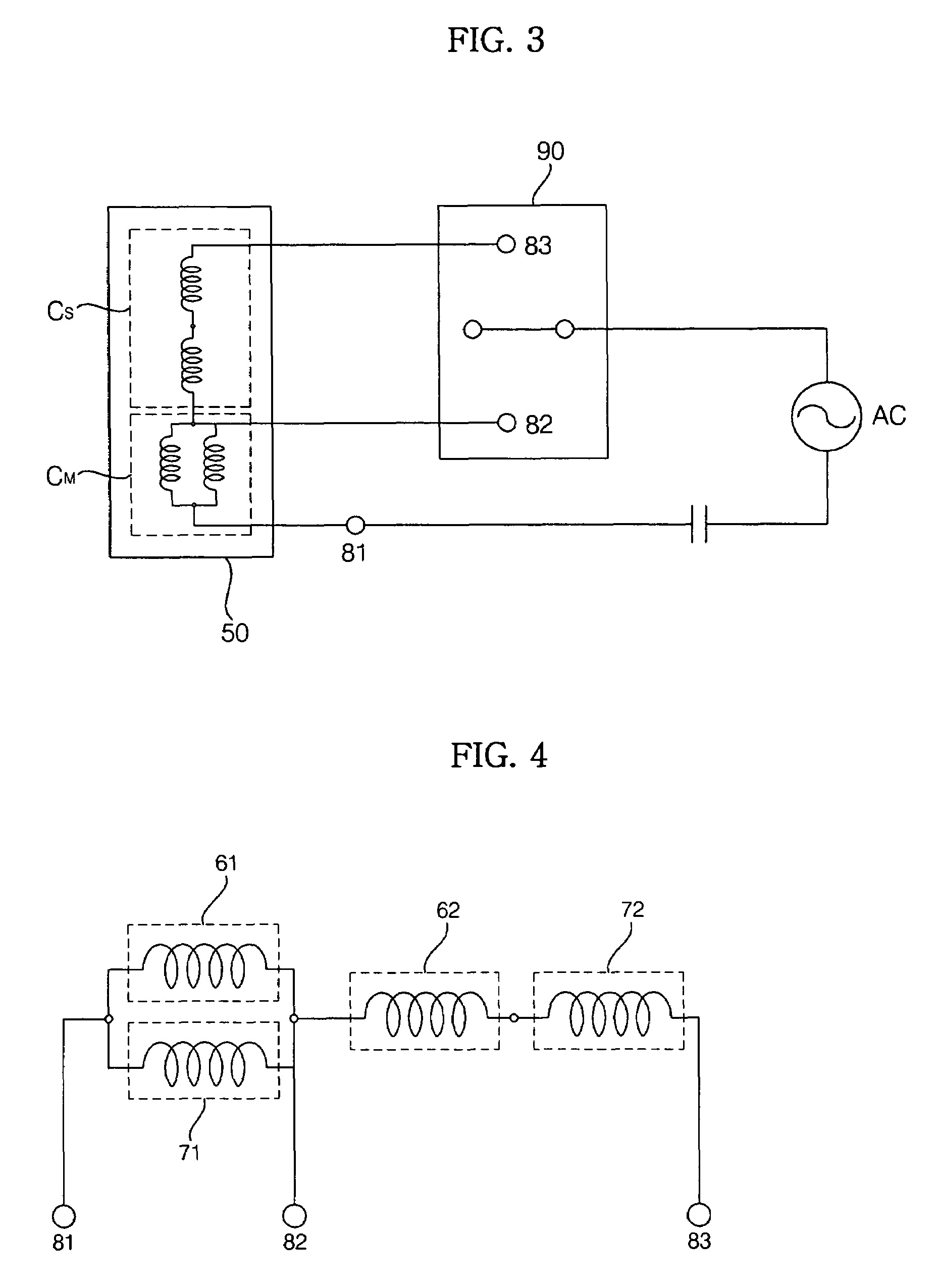
[0038]FIG. 3 is a circuit diagram of a linear motor according to the present invention.

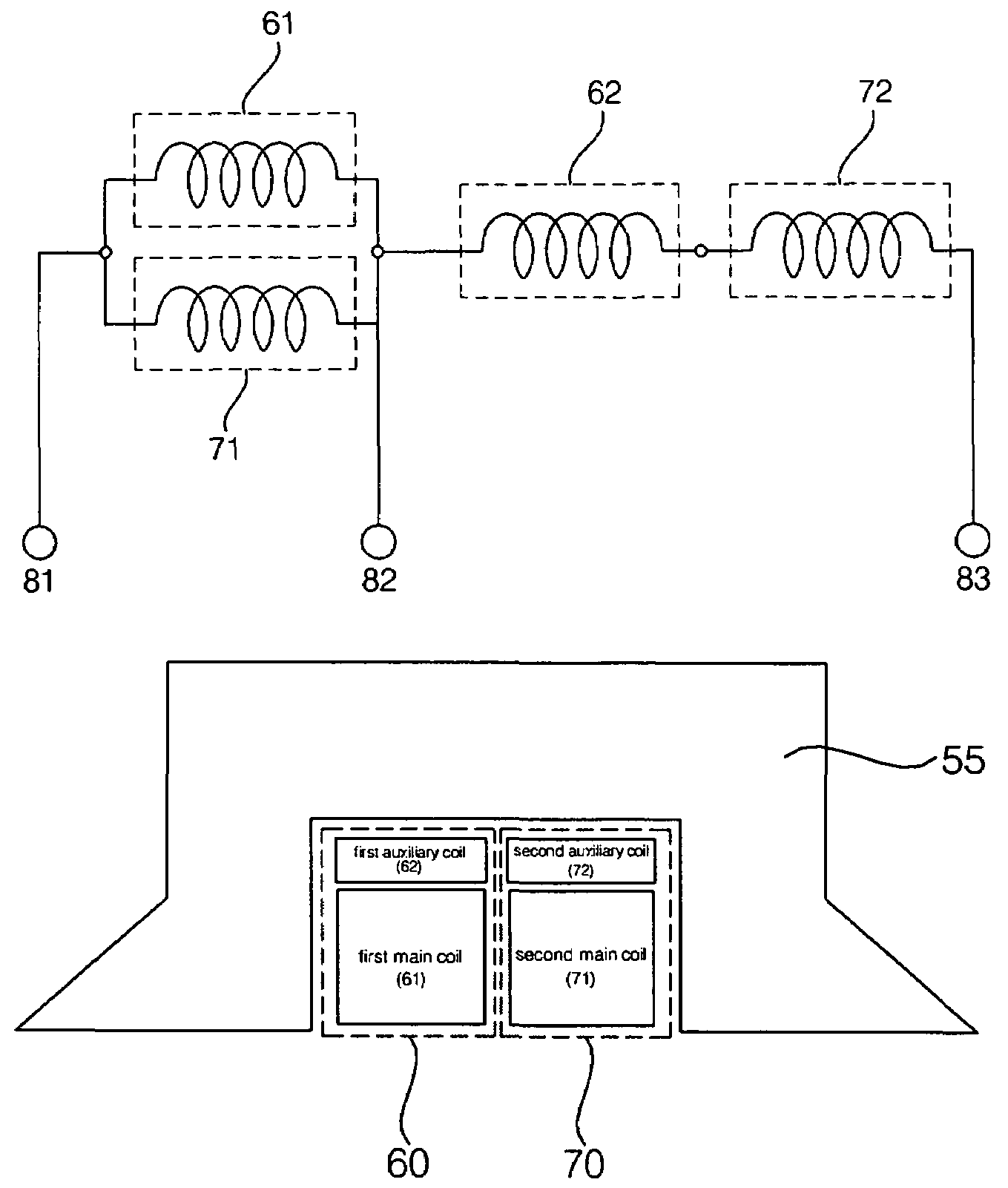
[0039]The linear motor according to the present invention comprises a power supply unit to apply AC power, supplied from an exterior source, to a linear motor body 50, the linear motor body 50 to perform a linear reciprocating movement upon receiving the AC power applied from the power supply unit, and a switch 90 connected between the linear motor body 50 and the power supply unit to apply the AC power from the power source to part or all of coils mounted in the linear motor body 50.

[0040]The lin...


PUM


Abstract

Disclosed herein is a linear motor in which a plurality of coil groups are connected in series or in parallel and driving power is applied to part or all of the coil groups according to load applied to the linear motor, thereby achieving improved motor efficiency with a reduced motor size. The linear motor includes a bobbin, the plurality of coil groups wound on the bobbin, the plurality of coil groups being connected in series or in parallel to allow the driving power to be applied to part or all of the coil groups, and a magnet adapted to be linearly reciprocated by a magnetic field produced by the coil groups depending on load current flowing through the coil groups. As a result of connecting the plurality of coil groups, which are formed of a plurality of coil conductors, in series or in parallel, the capacity of the coil groups is variable depending on the load of the motor, resulting in improved motor efficiency. Also, using the coil conductors having a small cross sectional area enables reduction in the size of the motor.

Description

BACKGROUND OF THE INVENTION[0001]1. Field of the Invention[0002]The present invention relates to a linear motor and a linear compressor using the same, and, more particularly, to a linear motor and a linear compressor using the same wherein a plurality of coil groups, provided in the linear motor, are connected in series or in parallel, and driving power is applied to part or all of the coil groups depending on the magnitude of load current applied to the linear motor, whereby the linear motor achieves an improved efficiency with a reduced size.[0003]2. Description of the Related Art[0004]Generally, a compressor is an apparatus to compress fluid, such as air or gaseous refrigerant. In particular, a linear compressor is designed to introduce, compress, and discharge gaseous refrigerant through a linear reciprocating movement of a piston in a cylinder, which is performed by a linear driving force of a linear motor.[0005]Conventionally, the linear compressor comprises a hermetic contai...

Claims


Application Information

Patent Timeline
Patent Type & Authority Patents(United States)
IPC IPC(8): H02K33/16H02P7/00F04B35/04H02P25/06H02P25/064
CPCF04B35/045H02K33/06H02P25/027H02P25/032H02K41/02
Inventor JEONG, SANG-SUBLEE, HYUK
Owner LG ELECTRONICS INC
Why Eureka
Try Eureka