Wireless landing gear monitoring system

a monitoring system and landing gear technology, applied in the field of aircraft landing gear, can solve the problems of increasing the installation complexity of the monitoring system, increasing the cost of wiring, and significant contribution to aerodynamic noise and drag

Active Publication Date: 2009-02-17
THE BOEING CO
View PDF21 Cites 29 Cited by
  • Summary
  • Abstract
  • Description
  • Claims
  • Application Information

AI Technical Summary

Problems solved by technology

This wiring is costly, weight intensive, adds complexity to the installation of the monitoring systems, and can make a significant contribution to aerodynamic noise and drag.
In addition to the problems presented by the wiring, known systems often have difficulty transmitting signals across a rotating interface between the stationary axle and a revolving wheel.
Furthermore, known systems are prone to mechanical wear and are very sensitive to backlash that can degrade the performance of an aircraft's antiskid braking system.

Method used


Image

  • Wireless landing gear monitoring system
  • Wireless landing gear monitoring system
  • Wireless landing gear monitoring system

Examples


Embodiment Construction

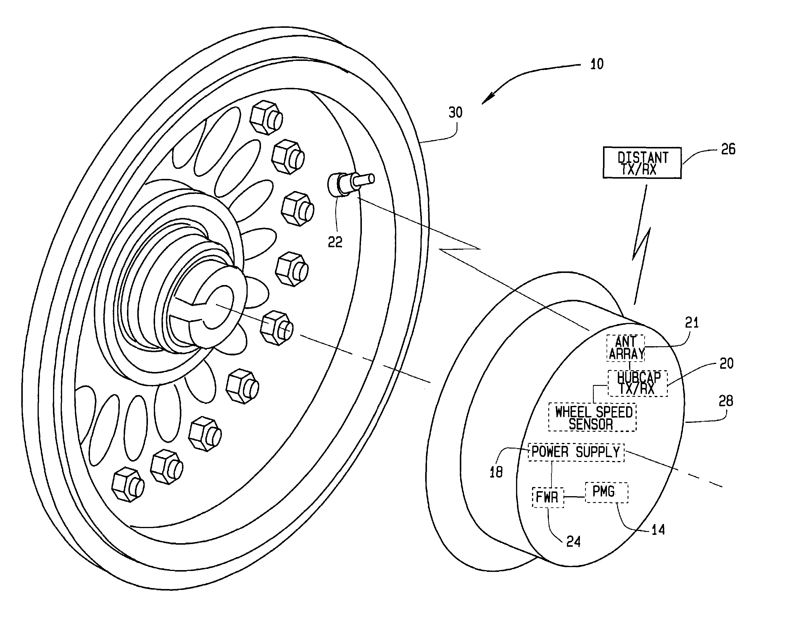
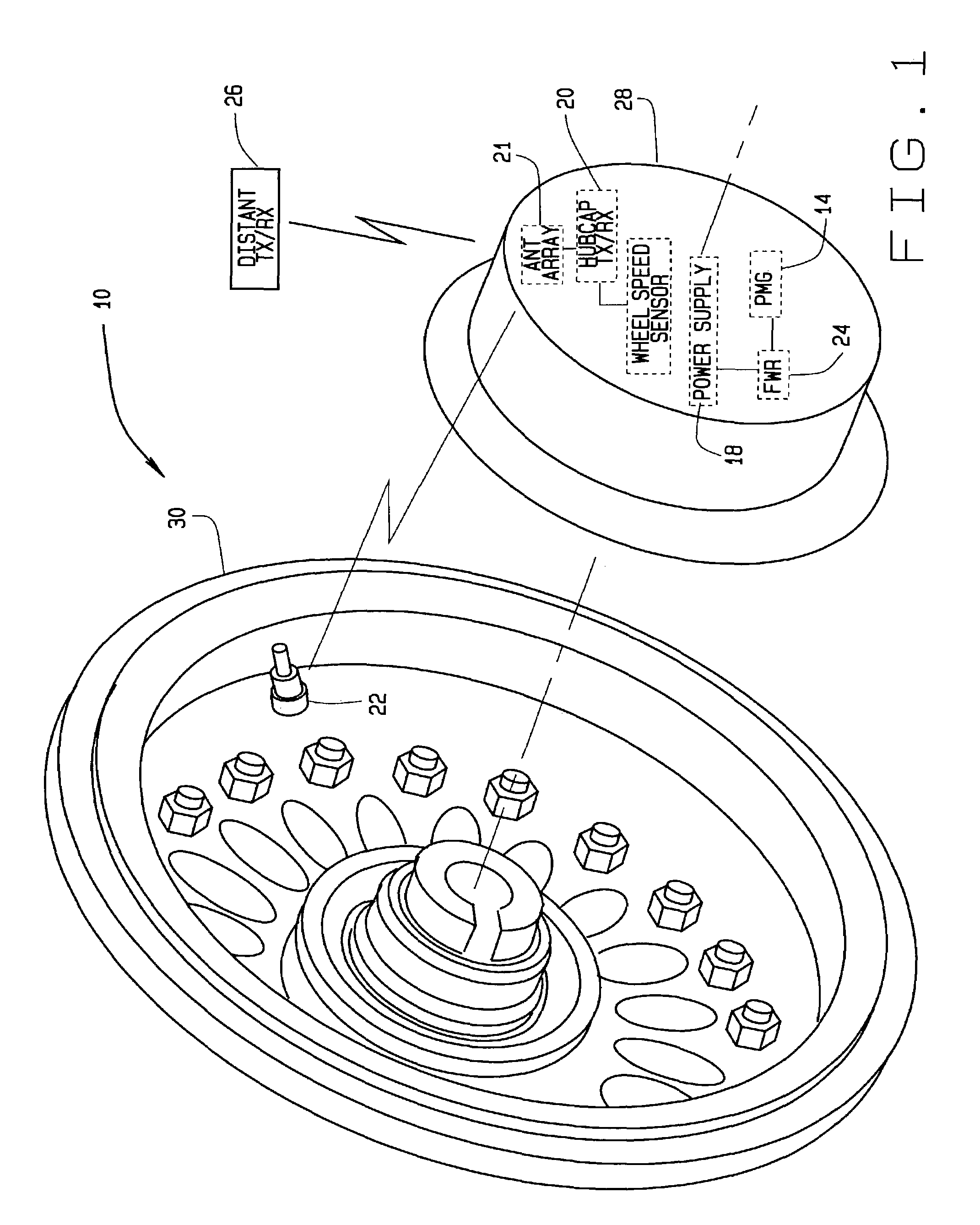
[0017]FIG. 1 is a schematic of a wireless aircraft landing gear monitoring system 10 in accordance with a preferred embodiment of the present invention. System 10 is used to monitor the operational status of landing gear systems. For example, monitoring system 10 is used to monitor landing gear wheel speed and tire pressure. However, it will be appreciated that while system 10 is ideally suited for aircraft landing gear, system 10 could be adapted for use with wheel assemblies of virtually any mobile platform, and is therefore not limited to use with only aircraft.

[0018]The components of monitoring system 10 include a permanent magnet generator (PMG) 14, a wheel speed sensor, or transducer, 16, a power supply 18, a radio frequency (RF) hubcap transceiver 20, an antenna array 21, a tire pressure sensor 22, a full wave rectifier (FWR) 24, and a distant (i.e. remote) transceiver 26. PMG 14, wheel speed sensor 16, power supply 18, RF hubcap transceiver 20, tire pressure sensor 22, and F...


PUM


Abstract

A wireless landing gear monitoring system for an aircraft. The monitoring system includes a radio frequency (RF) wireless hubcap transceiver powered by a rechargeable battery combined with a super-capacitor, all mounted to an inside surface of a wheel hubcap of the aircraft. Additionally, the system includes a permanent magnet generator (PMG) mounted to the inside surface of the hubcap that charges the battery when the wheel is rotating. The hubcap transceiver communicates with at least one distant, or remote, transceiver inside the aircraft, a tire pressure sensor mounted to a wheel rim, and a Hall-effect wheel speed transducer mounted to the hubcap. The tire pressure sensor uses an extremely low power RF transmitter to communicate with the hubcap transceiver, which then sends wheel speed and tire pressure data to the distant transceiver.

Description

FIELD OF INVENTION[0001]The invention relates generally to aircraft landing gear. More specifically, the invention relates to a wireless system and method for monitoring tire pressures and wheel speeds of aircraft landing gear.BACKGROUND OF THE INVENTION[0002]Known systems and methods for measuring aircraft tire pressures and wheel speeds require wiring to be run from a control unit inside the aircraft down a landing gear strut and into the inside of an axle. Holes have to be made in a landing gear beam to accommodate the wiring that runs from an antiskid system and tire pressure indication system mounted inside the axle to the control unit. This wiring is costly, weight intensive, adds complexity to the installation of the monitoring systems, and can make a significant contribution to aerodynamic noise and drag.[0003]In addition to the problems presented by the wiring, known systems often have difficulty transmitting signals across a rotating interface between the stationary axle a...

Claims


Application Information

Patent Timeline
Patent Type & Authority Patents(United States)
IPC IPC(8): B64C25/34B60C23/04B64C25/36B64D45/00
CPCB60C23/0408B60C23/041B64C25/36B64D45/0005B60C2200/02G01P3/488B60C23/042B60C23/0483
Inventor MACKNESS, ROBERT F.
Owner THE BOEING CO
Why Eureka
Try Eureka