Pressurized bearing system for submersible motor

a technology of bearing system and submersible motor, which is applied in the direction of piston pump, positive displacement liquid engine, borehole/well accessories, etc., can solve the problems of premature wear and motor failure, excessive motor vibration, and insufficient pressure of circulation created by prior art patents to create fluids

Inactive Publication Date: 2009-02-17
BAKER HUGHES INC
View PDF24 Cites 35 Cited by
  • Summary
  • Abstract
  • Description
  • Claims
  • Application Information

AI Technical Summary

Benefits of technology

[0008]The lubricant flows through the first diffuser and into the inlet of the first impeller. The lubricant then flows through the second diffuser and second impeller and flows out of the outlet of the second impeller into a reservoir. The first stage pressurizes the lubricant to a pressure level, and the second stage pressurizes the lubricant to a second, higher pressure level. The pressure in the reservoir causes the lubricant to flow through the hollow shaft and through the outlets to the bearings. Each outlet has at least three ports arranged generally symmetrically around the shaft. The lubricant is pressurized to a pressure sufficient to induce a film of lubricant between the shaft and the bearings, the film preventing the shaft from contacting the bearings, thus stabilizing the bearings.

Problems solved by technology

This causes instability in the bearings, which can result in excessive motor vibration.
Excessive vibration in the bearings can cause the bearing sleeves to break through the lubricant film, resulting in metal-to-metal contact that can lead to premature wear and motor failure.
The circulation created by the prior art patents would not appear to provide sufficient pressure to create a fluid film between the bearings and the shaft.
While some pressure is developed in an ESP motor designed for lubricant circulation, it is much too low to achieve stabilization of the bearing through fluid film stabilization.

Method used


Image

  • Pressurized bearing system for submersible motor
  • Pressurized bearing system for submersible motor
  • Pressurized bearing system for submersible motor

Examples


Embodiment Construction

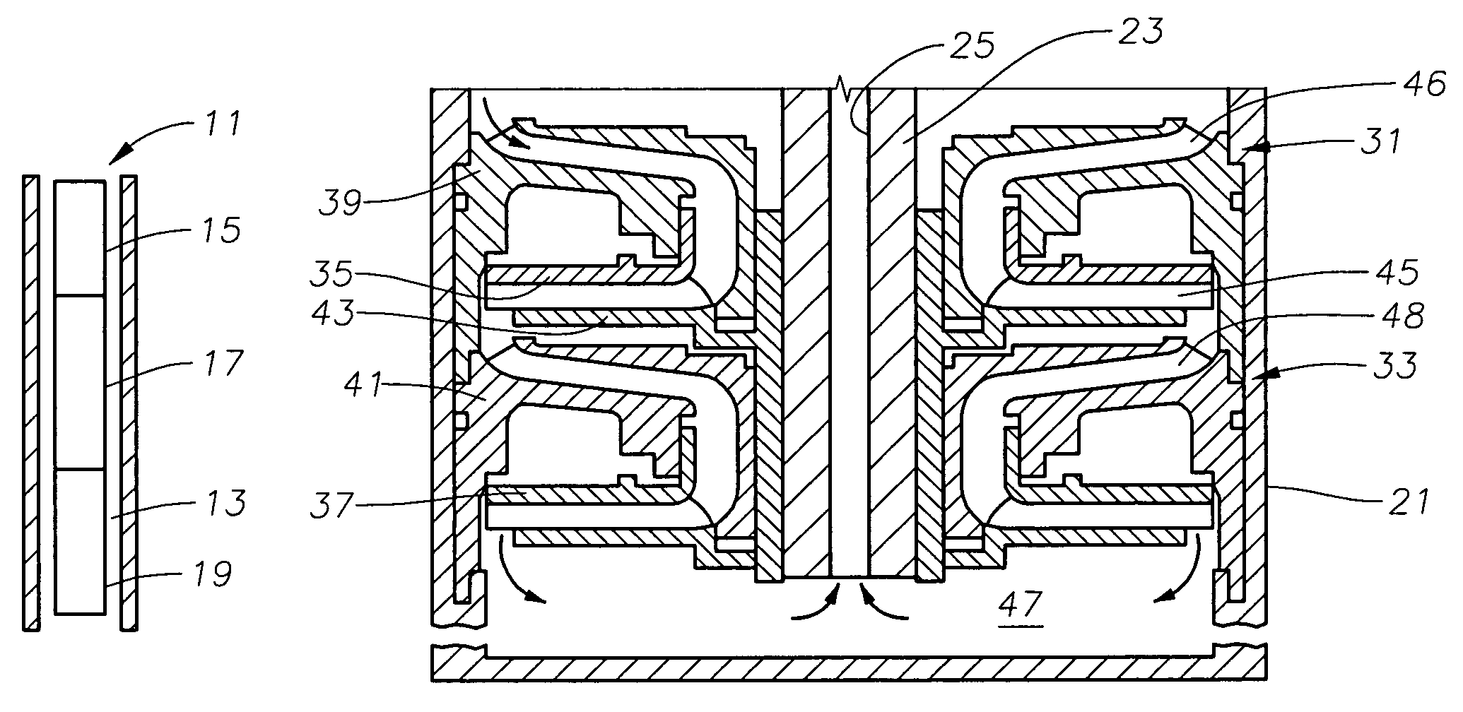
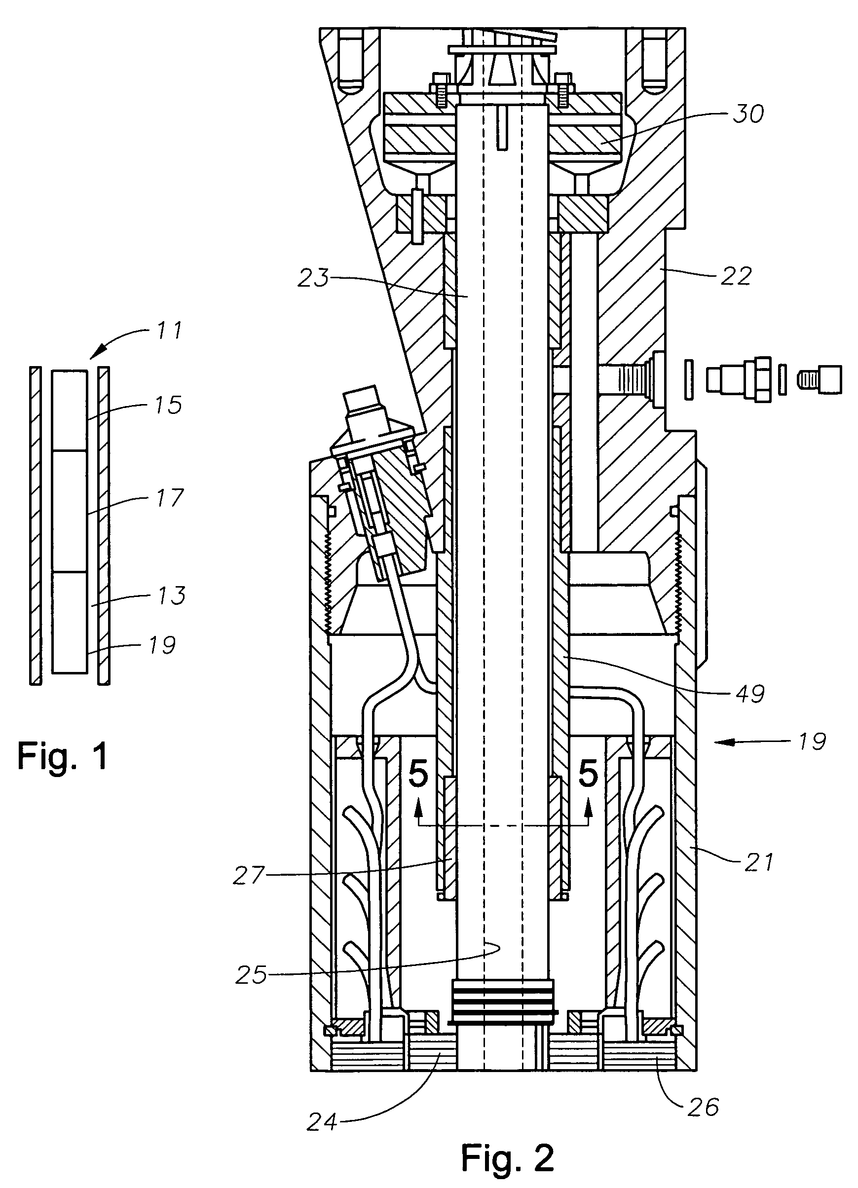
[0016]Referring to FIG. 1, a downhole, electric, submersible pump (ESP) assembly 11 is shown installed in a well 13. ESP assembly 11 comprises a pump 15, a seal section 17, and a motor 19. Pump 15 is used to pump well fluids from within the well to the surface. Pump 15 may be a centrifugal pump having a plurality of stages, each stage having an impeller and a diffuser for imparting an upward force to the fluid. Alternatively, pump 15 may be a progressive-cavity pump having an elastomeric stator and a metal rotor that rotates within the stator. Seal section 27 reduces pressure differential between the hydrostatic pressure in the well and the pressure of lubricant contained in motor 19. Motor 19 is connected to a source of electricity by a cable or other means (not shown) for powering motor 19. Drive shaft 23 (FIG. 2) of motor 19 is coupled to shafts (not shown) within seal section 17 and pump 15 to transfer torque from motor 19 to pump 15. Motor 19 creates a torque on shaft 23 to cau...


PUM


Abstract

Pressurized lubricant is used for stabilizing shaft bearings in an electrical submersible pump motor. A lubricant pump is located within the motor housing. The lubricant pump has a set of impellers attached to a lower end of the shaft and rotating with the shaft, the impellers being located in the flow path of the lubricant. A diffuser is located upstream of and adjacent each impeller. The impellers increase the radial velocity of the lubricant, and this velocity is converted into a pressure head at the impeller outlet. The lubricant flows through the first diffuser, through the first impeller, through the second diffuser, and then flows through the second impeller and out into a reservoir. The shaft has an axial flow passage with an outlet at each bearing. The outlet has at least three ports arranged symmetrically around the shaft for discharging lubricant into a clearance between the shaft and bearing to create a fluid film.

Description

CROSS-REFERENCE TO REALTED APPLICATION[0001]This application is a continuation-in-part of application Ser. No. 10 / 684,969, filed Oct. 14, 2003, abandoned, which was a continuation of Ser. No. 09 / 838,741, filed Apr. 19,2001, abandoned.FIELD OF THE INVENTION[0002]This invention relates generally to electrical submersible pump assemblies and particularly to a pump assembly having an internal lubricant pump in the motor that pressurizes the lubricant to stabilize bearings for the motor shaft.BACKGROUND OF THE INVENTION[0003]A conventional, electric, submersible pump (ESP) assembly includes an electrical motor and a rotary pump that is used to pump oil or other fluids from a well. The motor has a rotatable rotor that is contained within a stationary stator. The rotors for the submersible pumps are usually disposed in substantially vertical position by virtue of the wells often being vertical. The rotor shafts may be 30 feet or more in length, thus need radial support bearings to stabiliz...

Claims


Application Information

Patent Timeline
Patent Type & Authority Patents(United States)
IPC IPC(8): H02K5/12F01D3/00F04D13/10F04D29/06F16C33/10H02K5/10H02K5/132H02K7/08
CPCF04D13/10F04D29/044F04D29/047F04D29/061F16C33/1085H02K7/08H02K7/083H02K5/10H02K5/132H02K16/02F04D13/12
Inventor KNOX, DICK L.SOUKUP, GEORGE C.
Owner BAKER HUGHES INC
Why Eureka
Try Eureka