
Mobile solar generator

a solar generator and mobile technology, applied in solar thermal energy generation, solar heat collector controllers, starter details, etc., can solve the problem that the cart disclosed by azzam is not effective enough to supply enough energy

Inactive Publication Date: 2009-02-17
BENN WILLIAM M +1
View PDF25 Cites 97 Cited by
  • Summary
  • Abstract
  • Description
  • Claims
  • Application Information

AI Technical Summary

Benefits of technology

The system provides a cost-effective, mobile, and flexible solution for generating electricity, capable of powering a residence independently and reducing utility grid reliance, with a lower upfront cost compared to traditional installations.

Problems solved by technology

However, the cart disclosed by Azzam is inadequate for effectively supplying enough energy to satisfy the needs of a typical residence.

Method used


Image

  • Mobile solar generator
  • Mobile solar generator
  • Mobile solar generator

Examples


second preferred embodiment

[0035]In the first preferred embodiment, PV modular platform was shown as a single power generation unit. In the second preferred embodiment, two auxiliary PV modular platforms are added to a main PV modular platform 1. The auxiliary PV modular platform is similar in design to PV modular platform 1 described above with the exception that the auxiliary PV modular platform preferably does not contain an inverter. The inverter is unnecessary because the DC current from the auxiliary unit will feed directly into the main PV modular platform 1 at via switch 112 (FIG. 8).

[0036]By connecting two auxiliary PV modular platforms to PV modular platform 1, the entire system can provide approximately 1.2 kilowatts, this is enough to power a house. It is estimated that the total purchase price for two auxiliary PV modular platforms and a main PV modular platform is approximately $11,000. If the current monthly electric bill for a residential electricity user is $300 / month, it will take slightly m...

third preferred embodiment

[0037]A third preferred embodiment is shown in FIG. 11. The third preferred embodiment is similar to the embodiment shown in FIG. 8, except that AC sub panel 120 is replaced with programmable circuit selection panel 200.

Programmable Logic Controller (PLC)

[0038]PLC 203 is programmed to monitor the utility grid. Multi-meter 201 reports the status of the utility grid to PLC 203. If the utility grid is not energized (i.e., no current is detectable from the utility grid), PLC 203 opens switch 202. Modular platform 1 (FIG. 1) then becomes disconnected from the utility grid so that it operates as a stand alone power supply system to the load. PLC 203 will continue to monitor the status of the utility grid. Once PLC 203 determines the utility grid is back on line, PLC 203 will close switch 202 so that AC monitor panel 122 is once again receiving inputs from both modular platform 1 and the utility grid.

Programmable Circuit Selection Panel

[0039]Programmable circuit selection panel 200 include...

fourth preferred embodiment

[0042]A fourth preferred embodiment of the present invention is shown in FIGS. 12-14. In the fourth preferred embodiment battery cables 206 and 207 are connected to each other by utilization of quick release connection device 208.

[0043]Attached to the end of cable 206 are female connection prongs 209. Attached to the end of cable 207 is male connection prong 210. As shown in FIG. 12, male prong 210 is inserted partway between female prongs 209. Cam clip 211 is in the position shown in FIG. 12. Cam tension adjustment nut 212 (which includes spring 213) is pivotally connected to cam clip 211. Spring 213 is relaxed and connects cam tension adjustment nut 212 to cam tension adjustment strap 214.

[0044]In FIG. 13, male prong 210 has been inserted further into female prongs 209. Cam clip 211 has been rotated upward. Spring 213 is now under tension causing cam clip 211 and cam tension adjustment strap 214 to exert a compressive force on female prongs 209. Male prong 210 is now securely sque...


PUM

PropertyMeasurementUnit
weightaaaaaaaaaa

Abstract

A portable PV modular solar generator for providing electricity to a stationary electrically powered device. A plurality of wheels is attached to a rechargeable battery container. The plurality of wheels allow for movement of the PV modular solar generator so that the distance can be varied between the PV modular solar generator can be positioned in optimum sunlight. There is a rechargeable battery contained inside the rechargeable battery container. There is a pivotally connected photovoltaic panel for generating electricity. There is an electrical component for receiving an processing electricity generated by the pivotally connected photovoltaic panel. The electrical component also directs the electricity to either the rechargeable battery for storage or to the stationary electrically powered device. The PV modular solar generator supplies energy to an AC main panel for the stationary electrically powered device. The AC main panel receives generated energy from a public utility grid. The PV modular solar generator also includes a computer for monitoring the status of the public utility grid. The computer is capable of disconnecting the public utility grid from the AC main panel when the public utility grid is not energized and computer is also capable of connecting the public utility grid to the AC main panel when the public utility grid is energized.

Description

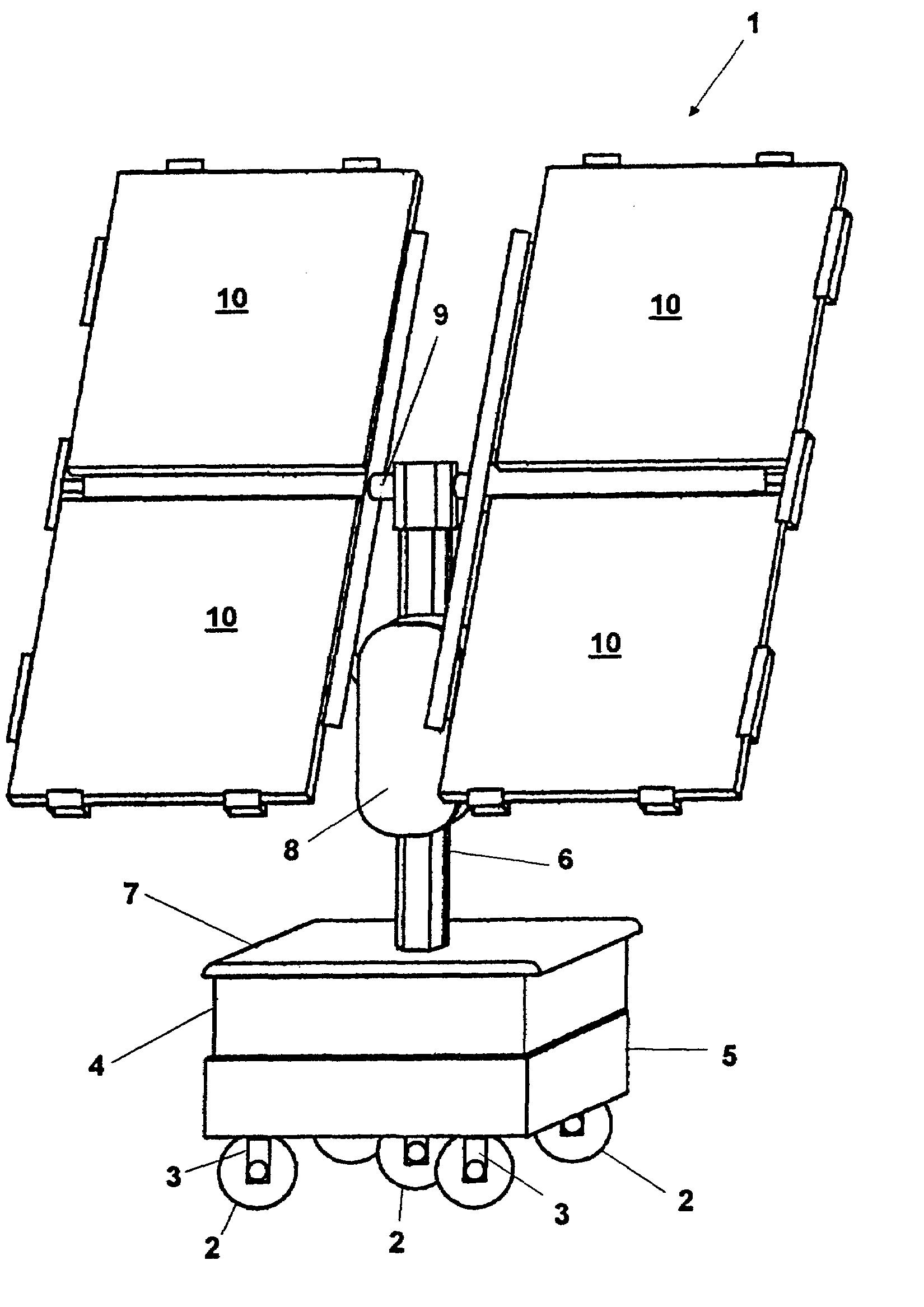
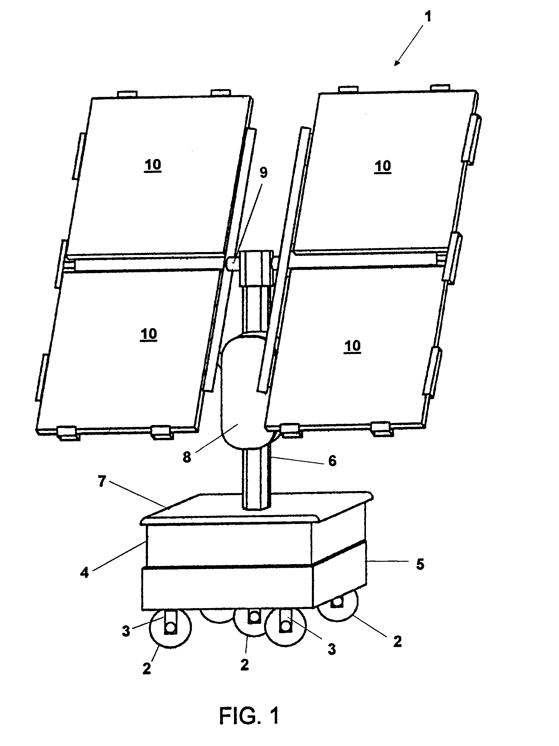
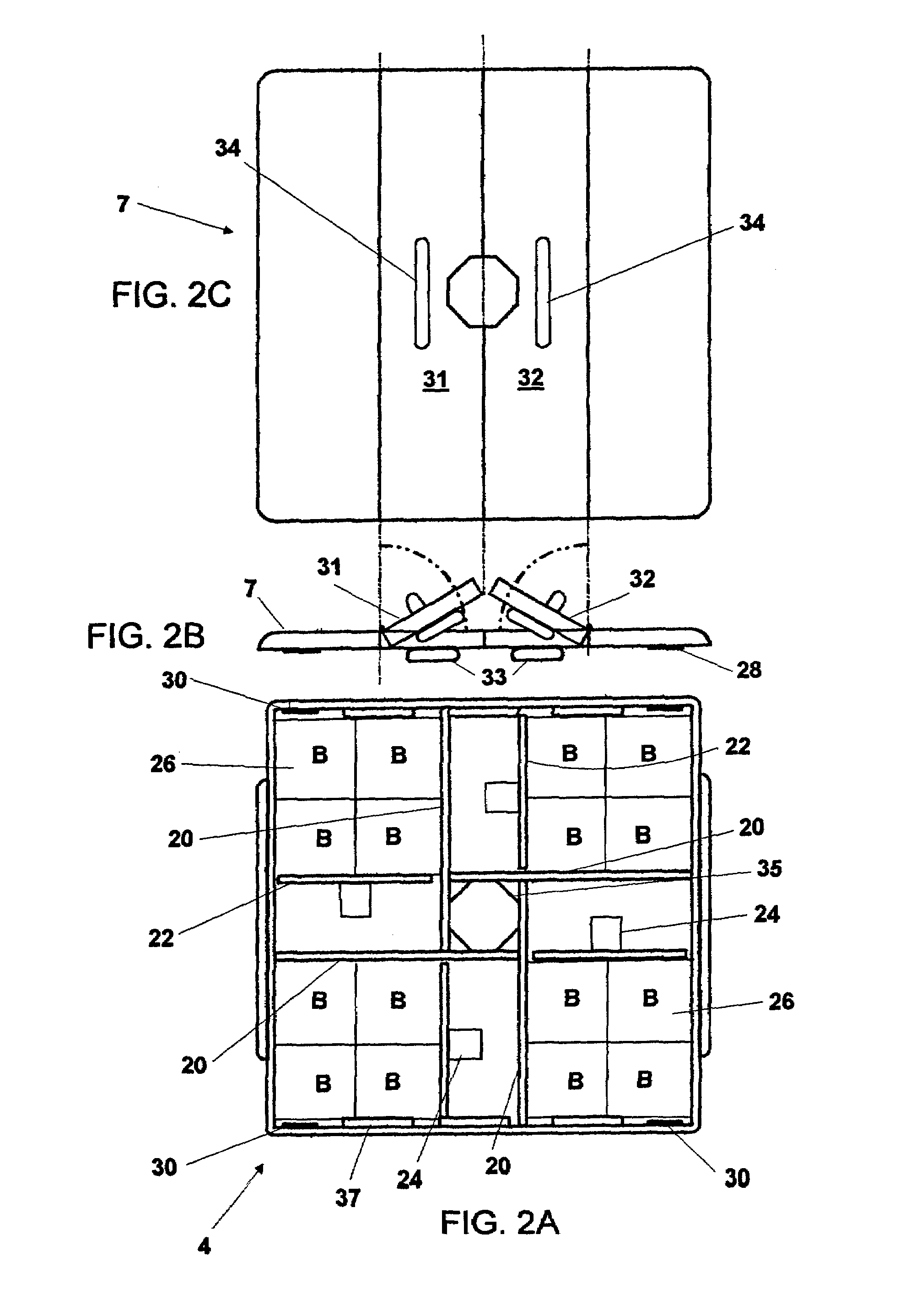
[0001]The present invention relates to solar electric generators, and in particular, to portable solar electric generators. The present invention is a continuation-in-part of U.S. patent application Ser. No. 09 / 828,114, filing date Apr. 6, 2001 now U.S. Pat. No. 6,396,239.BACKGROUND OF THE INVENTION[0002]In recent years, the cost of generating electricity has increased dramatically. In California, the monthly electric bill for many consumers has more than doubled in the past year. Rolling blackouts, a condition in which geographical sections of the community are alternately cut-off from receiving electricity during an electrical shortage crisis, are becoming increasingly commonplace. As our planet's natural resources are depleted and as population increases, the importance of effectively harnessing alternative methods of generating electricity has increased.Solar Energy[0003]Photovoltaic panels (also called solar panels) are well known and are used to generate electricity from sunli...

Claims


Application Information

Patent Timeline
Patent Type & Authority Patents(United States)
IPC IPC(8): H01M10/44H02J7/00F24J2/36H01L31/042F24J2/54F24S50/20H01M10/46H01M50/204H01M50/24H01M50/251H01M50/264H02J7/35H10N10/80
CPCF24J2/36H02S30/20F24J2/542H01M10/465H02J7/355F24J2/38H02S20/00F24J2002/5489H01M2/1016Y02B10/14Y02B10/20Y02E10/47Y02E10/50F24J2002/0084F24J2/523H02S20/30H02S10/40F24S2030/17F24S20/50F24S2020/16F24S50/20F24S25/10F24S30/452H02J7/35Y02B10/10Y02E10/56Y02E60/10H01M50/204H01M50/264H01M50/251H01M50/24
Inventor BENN, WILLIAM M.BENN, JOHN T.
Owner BENN WILLIAM M
Learn More