Transmitter head and system for contactless energy transmission

a technology of contactless energy transmission and transmitter head, which is applied in the direction of transformers, coils, relays, etc., can solve the problems of low energy transmission efficiency, and achieve the effect of small unit volume, inexpensive and uncomplicated manner

Active Publication Date: 2009-02-17
SEW-EURODRIVE GMBH & CO KG
View PDF7 Cites 268 Cited by
  • Summary
  • Abstract
  • Description
  • Claims
  • Application Information

AI Technical Summary

Benefits of technology

[0006]An example embodiment of the present invention may provide a system for contactless energy transmission which may provide a smaller unit volume in an inexpensive and uncomplicated manner.

Problems solved by technology

German Published Patent Application No. 197 46 919 describes a flat arrangement which, however, may result in low efficiency in the energy transmission.

Method used


Image

  • Transmitter head and system for contactless energy transmission
  • Transmitter head and system for contactless energy transmission
  • Transmitter head and system for contactless energy transmission

Examples


Embodiment Construction

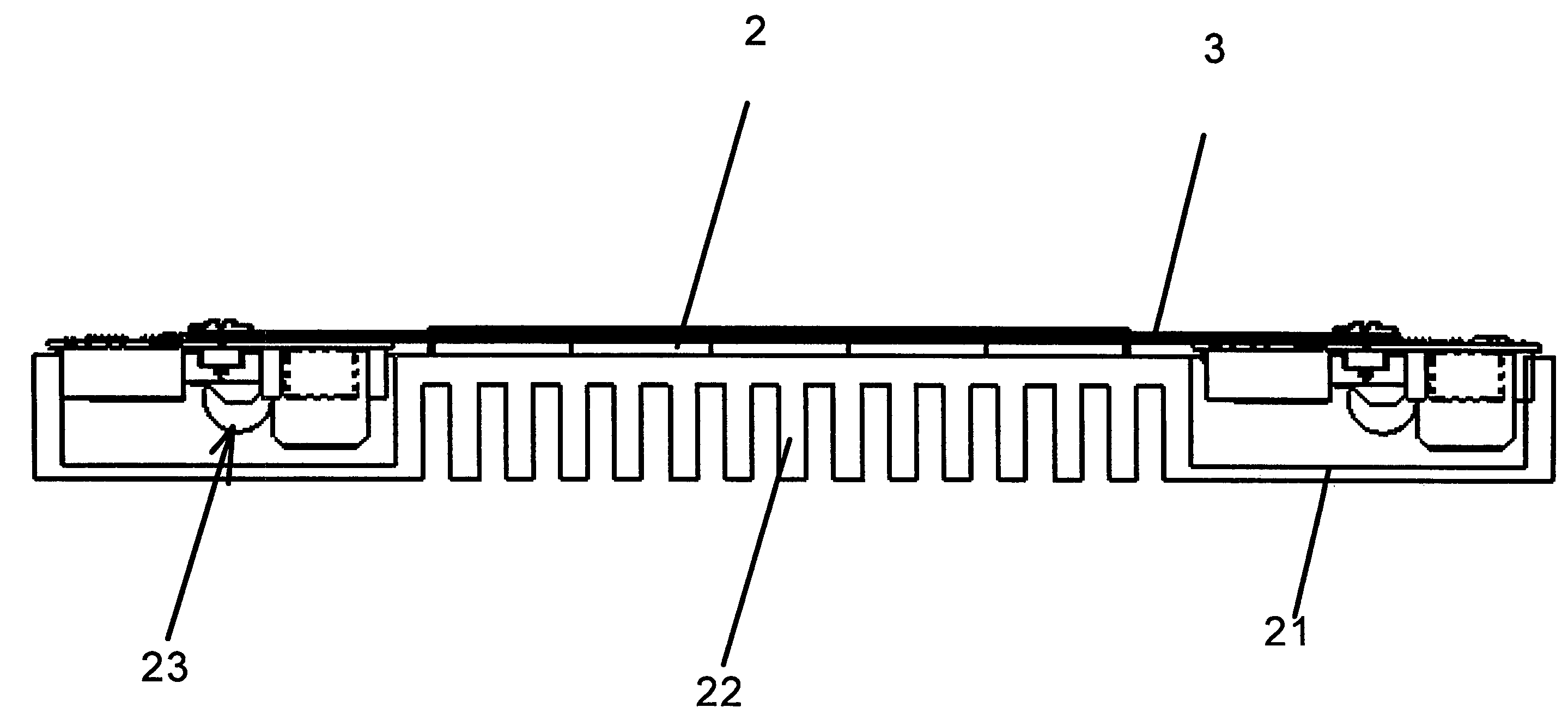
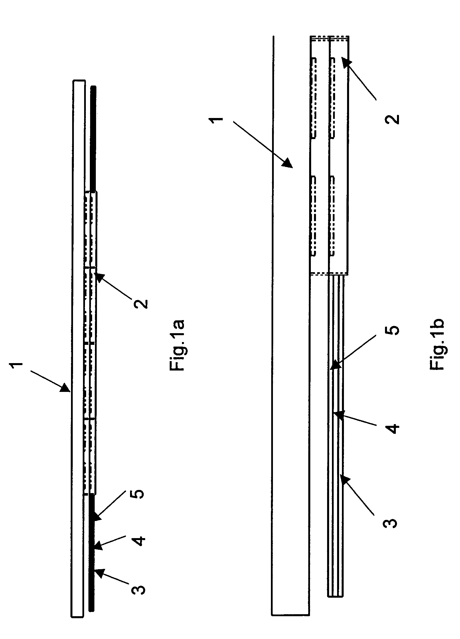
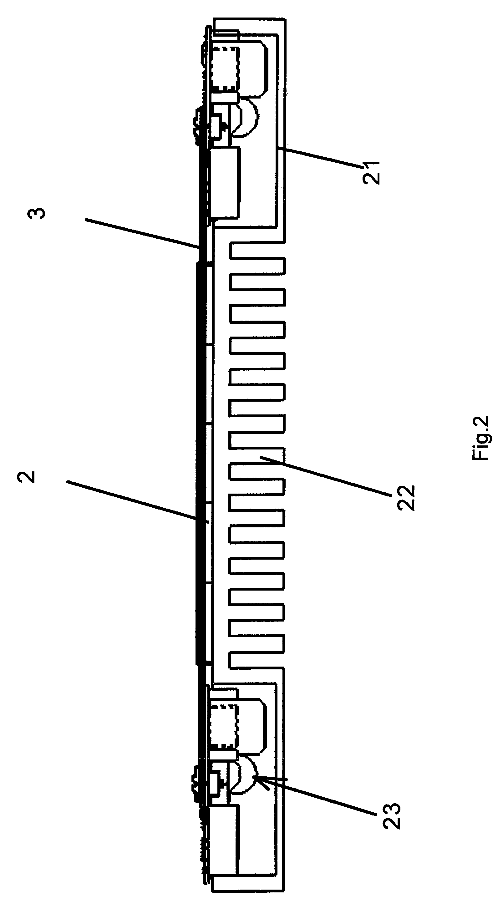
[0043]FIG. 1a illustrates a transmitter head of an example embodiment of the present invention, an enlarged section of the left end area being illustrated schematically in FIG. 1b. It may be flat and may need a small unit volume.

[0044]Ferrite cores 2 are mounted on and connected to support 1, using, for example, an adhesive connection or a releasable connection such as a screw connection, etc.

[0045]Provided at ferrite cores 2 is a multilayer board having layers (3, 4, 5) which bear copper conductor tracks that take the form of flat windings, and thus are implemented on the board.

[0046]In an exemplary embodiment of the present invention, a single, planar, spiral winding may be provided as a conductor track of a single-layer board, less electrical power then being transmittable, however.

[0047]In exemplary embodiments of the present invention, such as illustrated, for example, in FIGS. 1a and 1b, a multilayer board (3, 4, 5) is used that has a spiral winding in several planes. In that ...


PUM

PropertyMeasurementUnit
mutual distanceaaaaaaaaaa
distanceaaaaaaaaaa
surface normalaaaaaaaaaa

Abstract

A transmitter head for a system for contactless energy transmission includes a support connected to at least one ferrite core. The ferrite core is embodied at least partially in the E-form and a flat winding is arranged around one leg of the E.

Description

FIELD OF THE INVENTION[0001]The present invention relates to a transmitter head and a system for contactless energy transmission.BACKGROUND INFORMATION[0002]German Published Patent Application No. 100 53 373 describes a device for contactless energy transmission, in which a transmitter head permits inductive energy transmission and has a number of turns per unit length.[0003]German Published Patent Application No. 44 46 779 and German Published Patent Application No. 197 35 624 describe a system for contactless energy transmission, in which the path is made up of a stationary neutral conductor, and an aluminum profile as a return line. The neutral conductor is surrounded by a U-shaped core of the transmitter head, the core being movable along the neutral conductor. A winding is provided on the U-shaped core. The transmitter head may require a large unit volume.[0004]PCT International Published Patent Application No. WO 92 / 17929 describes a system for contactless energy transmission,...

Claims


Application Information

Patent Timeline
Patent Type & Authority Patents(United States)
IPC IPC(8): H01F5/00H01F17/00H01F19/08H01F38/14
CPCH01F17/0013H01F38/14H01F19/08H01F2038/143
Inventor SCHMIDT, JOSEFBECKER, GUNTERPODBIELSKI, LEOBALDNURGE, MARTIN
Owner SEW-EURODRIVE GMBH & CO KG
Why Eureka
Try Eureka