A Furnace Pool Structure for Reinforced Fiber Glass Melting Furnace

A glass melting furnace and fiber-reinforced technology, applied in the field of furnace pool structure, can solve problems such as affecting glass quality, and achieve the effects of enhancing cooling effect, reducing unit volume and improving cooling efficiency

Inactive Publication Date: 2017-06-09
重庆留鑫玻璃钢制品厂
View PDF0 Cites 0 Cited by
  • Summary
  • Abstract
  • Description
  • Claims
  • Application Information

AI Technical Summary

Problems solved by technology

[0004] The object of the present invention is to provide a furnace pool structure for strengthening fiber glass melting furnace, which prevents the pool wall wind from directly blowing into the lower gap and bringing sundries into the kiln to pollute the molten glass, so as to solve the problem of cooling the pool wall bricks. Problems Affecting Glass Quality

Method used


Image

  • A Furnace Pool Structure for Reinforced Fiber Glass Melting Furnace
  • A Furnace Pool Structure for Reinforced Fiber Glass Melting Furnace
  • A Furnace Pool Structure for Reinforced Fiber Glass Melting Furnace

Examples


Embodiment 1

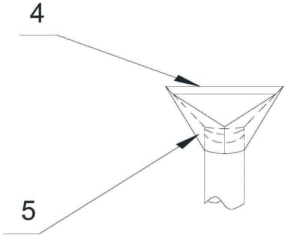
[0021] Such as Figure 1 to Figure 3 As shown, the present invention is a furnace pool structure for strengthening fiberglass melting furnaces, including an air duct 7 connected to a compressed air source and a pool wall tuyere 2, and the pool wall tuyere 2 is connected to the air duct through a curved portion 8 7 connection, the pool wall tuyere 2 is composed of the upper part 4 of the tuyere nozzle and the lower part 5 of the tuyere nozzle, the upper part 4 of the tuyere nozzle is a trapezoidal plate, and the longer bottom edge of the trapezoidal plate is connected with the outer wall of the pool wall brick 3, The short bottom edge of the trapezoidal plate is connected to the bent portion 8 , and the length of the upper part 4 of the air nozzle is greater than the length of the lower part 5 of the air nozzle. In order to ensure the life of the pool wall brick 3 and the quality of glass production, the glass kiln wall brick 3 needs to be continuously cooled and dissipated dur...

Embodiment 2

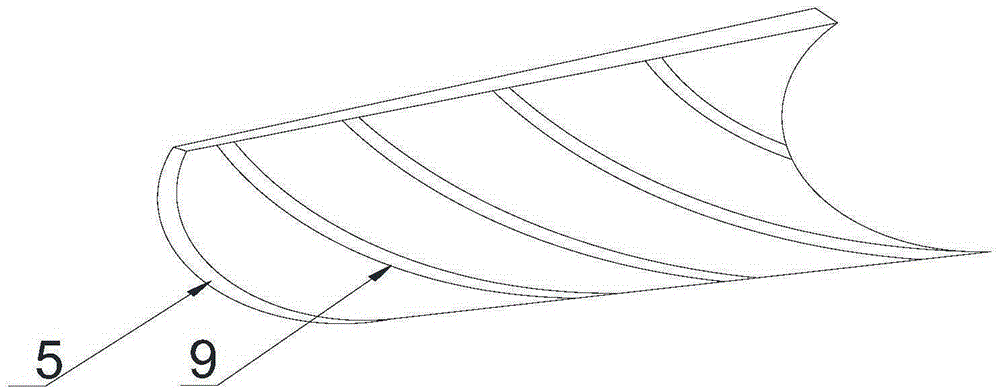
[0023] Such as figure 2 and image 3 As shown, in this embodiment, on the basis of Embodiment 1, a plurality of spiral grooves 9 are also provided in the lower part 5 of the tuyere, and the lower part 5 of the tuyere is an arc groove whose outer diameter decreases along the direction of the pool wall brick 3 Or V-groove. The multiple spiral grooves 9 arranged in the groove can make the mixed gas and the cooling air flowing in from the air inlet form a turbulent flow in the groove, thereby speeding up the flow speed of the cooling air and improving the cooling effect of the cooling air on the pool wall per unit time. The cooling efficiency of the brick 3; the lower part of the air nozzle 5 of the arc groove or the V-shaped groove can ensure the rapid flow of cooling air, and the outer diameter of the lower part of the air nozzle 5 decreases along the direction of the pool wall brick 3, which can make the unit volume of the cooling air suddenly decrease, the air velocity ejec...


PUM


Abstract

The invention discloses a furnace pool structure for strengthening fiber glass melting furnace, which includes an air duct connected with a compressed air source and a pool wall air nozzle, the pool wall air nozzle is connected with the air duct through a bent part, and the pool The wall air nozzle is composed of the upper part of the air nozzle and the lower part of the air nozzle. The upper part of the air nozzle is a trapezoidal plate. The longer bottom of the trapezoidal plate is connected with the outer wall of the pool wall brick. part connection, the length of the upper part of the tuyere is greater than the length of the lower part of the tuyere. The length of the upper part of the air nozzle is longer than the length of the lower part of the air nozzle, and the direct-flow cooling air flows out directly from the lower part of the groove-shaped air nozzle to cool down the pool wall bricks, so as to avoid the damage caused by the connection between the upper part of the air nozzle and the surface of the pool wall bricks. Cooling effect decreased.

Description

technical field [0001] The invention relates to the field of glass production, in particular to a furnace pool structure for strengthening fiberglass melting furnaces. Background technique [0002] Float glass is widely used, divided into colored glass, float silver mirror, float glass / car windshield grade, float glass / various deep processing grade, float glass / scanner grade, float glass / coating grade, float glass French glass / mirror grade. Among them, ultra-clear float glass has a wide range of uses and broad market prospects. It is mainly used in high-end buildings, high-end glass processing and solar photovoltaic curtain walls, as well as high-end glass furniture, decorative glass, imitation crystal products, lamp glass, precision electronics industry, special buildings, etc. The forming process of float glass production is completed in a tin bath fed with protective gas (N2 and H2). The molten glass flows continuously from the tank kiln and floats on the surface of the...

Claims


Application Information

Patent Timeline
Patent Type & Authority Applications(China)
IPC IPC(8): C03B18/18
Inventor 刘青
Owner 重庆留鑫玻璃钢制品厂
Why Eureka
Try Eureka