Adapter hingedly connecting a wiper blade to a wiper arm

a technology of adapter and wiper blade, which is applied in the direction of rod connection, coupling, vehicle cleaning, etc., can solve the problems of adapter not being able to detach from the suspension box, adapter cannot be used for vehicle cleaning, and high surface stress of articulated surfaces, so as to facilitate the assembly of the wiper blade and avoid appreciable wear. , the effect of narrowing the toleran

Inactive Publication Date: 2009-02-24
ROBERT BOSCH GMBH
View PDF9 Cites 37 Cited by
  • Summary
  • Abstract
  • Description
  • Claims
  • Application Information

AI Technical Summary

Benefits of technology

[0007]According to the invention, the clip has a locking nose that points in the direction of the bearing element and locks on an edge of the coordinating side wall of the suspension box during assembly. As a result, the adapter is connected with the suspension box in a torque-proof manner so that no relative movement is generated between the passages and circumference of the bearing part. The rotational movement required for the articulation takes place exclusively between the bearing bore hole of the adapter and the pin of the wiper arm. In this case, the bearing surfaces can be dimensioned large enough so that no appreciable wear occurs. Nevertheless, should the adapter have to be replaced, this is easily possible by detaching the clip and pulling the adapter out of the passages. Moreover, the adapter no longer needs to be aligned with the wiper arm during assembly of the wiper blade on the wiper arm.
[0008]In one embodiment of the invention, the second end of the bearing element is formed on a cap, which in an assembled state is adjacent with a bearing surface to the coordinating side wall of the suspension box and has at least one clip. The cap can fulfill several functions. To begin with, it keeps the bearing element from twisting in the passages and also covers the passages and the articulated bolt on the external side walls so that they are protected from moisture and dirt. In addition, on its outer side the cap can have a bearing surface for a bent end of a bridge of a wiper arm. This facilitates assembly of the wiper blade and makes narrower tolerances possible in the axial direction of the pin so that the wiper blade is better guided on the pin of the wiper arm.

Problems solved by technology

If the pin is pushed into the passage bore hole, the bearing element is no longer able to yield radially so that the adapter can no longer detach from the suspension box.
This is hampered by the fact that the locking nose must be aligned on the leg of the U-shaped profile.
Furthermore, the relative movement takes place between the relatively narrow guide surfaces and the low wall thicknesses of the passages, the consequence of which is a high surface stress of the articulated surfaces.

Method used


Image

  • Adapter hingedly connecting a wiper blade to a wiper arm
  • Adapter hingedly connecting a wiper blade to a wiper arm
  • Adapter hingedly connecting a wiper blade to a wiper arm

Examples


Embodiment Construction

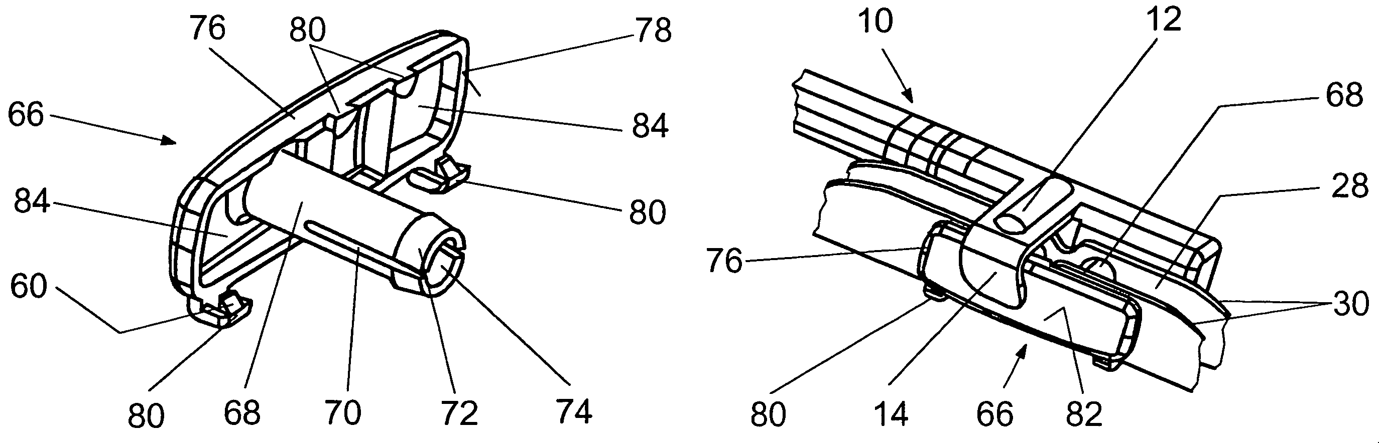
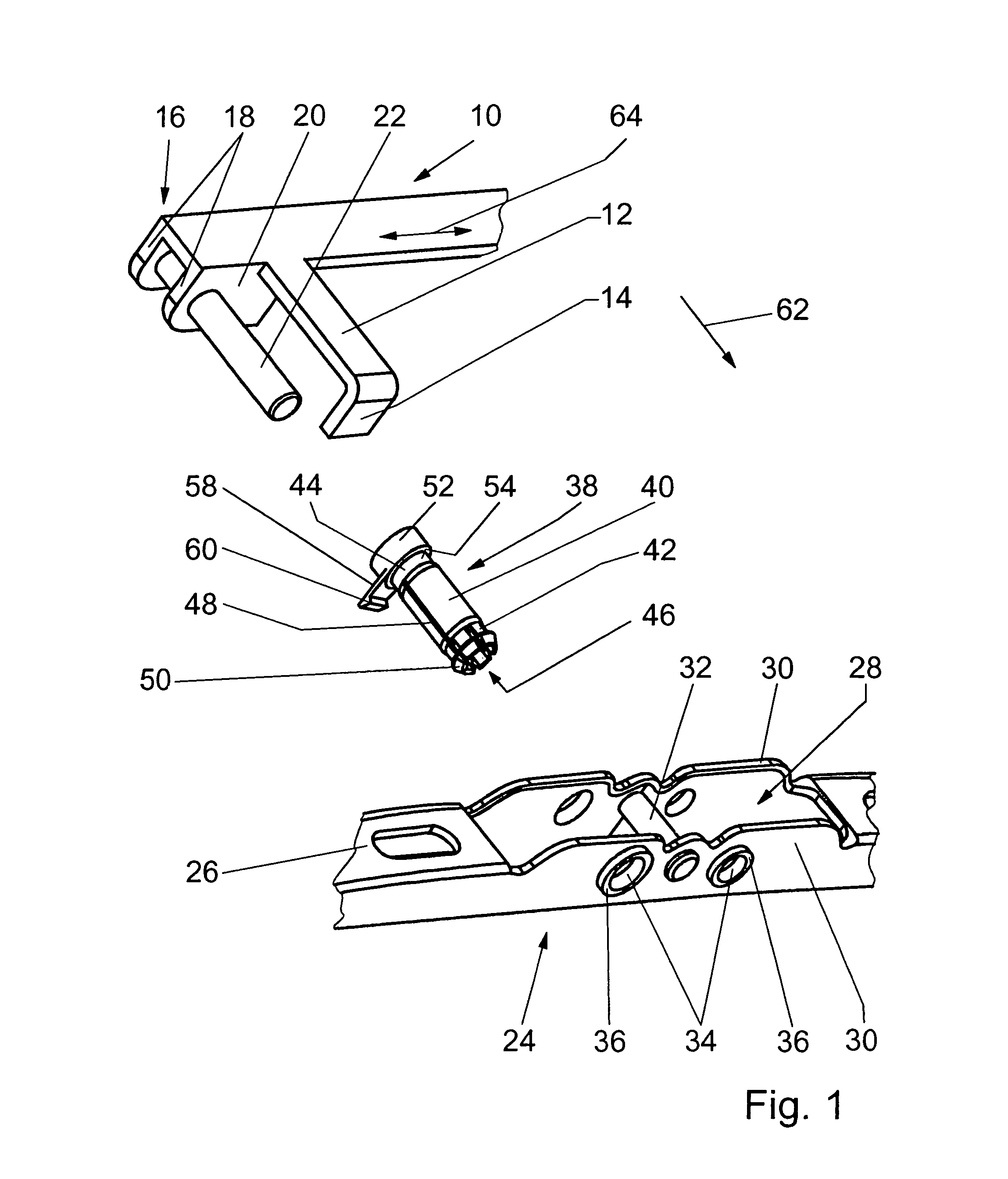
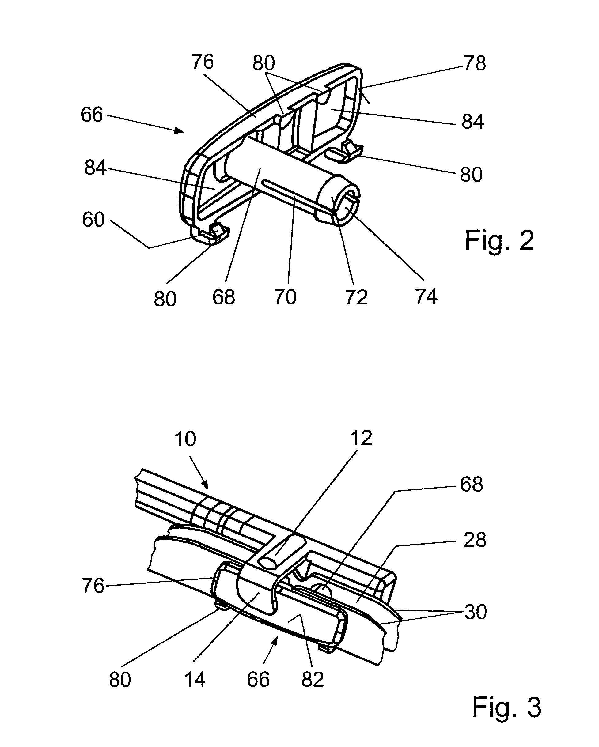
[0014]Of a windshield wiper, only the parts of a wiper arm 10 and a wiper blade 24 (FIG. 1) that are necessary for understanding the invention are depicted. The wiper arm 10 has a U-shaped profile 16, on whose legs 18 a pin 22 is laterally fastened transverse to the longitudinal direction 64 and pointing toward the wiper blade 24 so that the wiper blade 24 can be mounted using the sidelock system. Furthermore, a bridge 12 is formed on the free end of the wiper arm 10. This bridge is arranged parallel to the pin 22 offset in the longitudinal direction 64 relative to this pin and has a bent end 14. The wiper blade 24 has a supporting bracket system, a main bracket 26 of which is shown. This bracket has a suspension box 28 whose side walls 30 are connected to one another via an articulated bolt 32. In addition, on both sides of the articulated bolt 32 in the longitudinal direction 64, two opposing passages 34 each are offset in the side walls 30.

[0015]The wiper blade 24 is connected in...


PUM


Abstract

An adapter (38, 66) for the articulated connection of a wiper blade (24) to a wiper arm (10) using the sidelock system, wherein the adapter (38, 66) has an essentially cylindrical longitudinally slotted bearing element (40, 68), which can be inserted into passages (34) in side walls (30) of a suspension box (28) of the wiper blade (24) and can be fixed on a first end on the edge of a passage (34) by means of locking hooks (50), while its second end is connected with a bearing surface (54, 78), which is adjacent to the outer side of the opposing side wall (30) and is secured against twisting by at least one clip (58, 80). The clip (58, 80) has a locking nose (60), which points in the direction of the bearing element and locks on an edge of the coordinating side wall (30) of the suspension box (28) during assembly.

Description

BACKGROUND OF THE INVENTION[0001]The invention starts with an adapter for the articulated connection of a wiper blade to a wiper arm.[0002]Known windshield wipers feature a wiper arm, which sits on a wiper shaft. A wiper motor drives this shaft. A wiper blade is connected in an articulated manner with the free end of the wiper arm. The wiper blade as a rule has a multi-element supporting bracket system with a main bracket. Subordinate brackets are coupled to this system and at least several of these with claws on their ends hold a wiper strip. Non-articulated wiper blades are also known, which, instead of the supporting bracket system, have a resilient elastic supporting element perpendicular to the vehicle window, which is manufactured of plastic. In order to improve the springy property, it can feature at least one spring rail made of spring steel. The supporting element has a greater curvature than the vehicle window in an unstressed state so that the wiper strip is applied to th...

Claims


Application Information

Patent Timeline
Patent Type & Authority Patents(United States)
IPC IPC(8): B60S1/40B60S1/38
CPCB60S1/407B60S1/4074B60S2001/408Y10T24/42Y10T403/7058Y10T403/60
Inventor OP'T ROODT, INIGO
Owner ROBERT BOSCH GMBH
Why Eureka
Try Eureka