System and method for dynamic lubrication adjustment for a lubrication analysis system

Inactive Publication Date: 2009-02-24
ROCKWELL AUTOMATION TECH
View PDF67 Cites 20 Cited by
  • Summary
  • Abstract
  • Description
  • Claims
  • Application Information

AI Technical Summary

Benefits of technology

[0018]Dynamic adjustments to fluids can include adjusting fluid levels and chemical deficiencies in the fluids along with adjusting characteristics of the fluid based upon environmental considerations (e.g., making fluid adjustments according to duty cycle, load, and temperature of associated equipment). The sensor information can also be provided to external control systems to adjust operating characteristics in accordance with the current detected state of the fluids. For example, if a fluid were determined to be running hotter because of depletion, the sensor information can be employed to adjust the speed or torque of a controller and related equipment in order to extend the life of the lubricant.
[0019]Another aspect of the present invention includes utilizing the sensor information collected above to further enhance diagnostic and prognostic aspects of the present invention. This can include providing data quality metrics along with sensor information to indicate not only the operating characteristics of fluids but also to indicate information that relates to the health or status of the sensor reporting the fluid information. In this manner, equipment can be better maintained since information is provided according to the current operating status of the fluids indicating when corrective actions are needed. To further facilitate the process, predictive information is provided relating to the quality of the components that detect when the corrective actions are needed, thus increasing the overall confidence and accuracy of the system.
[0020]According to another aspect of the present invention, lubricant operating life is extended to further reduce maintenance and costs associated with lubricant replacement. This can be achieved by exciting one or more electrodes via excitation pulses to reduce oxidation present in the lubricants. In addition, other processes can include energizing one or more magnetic or other type structures to facilitate removal of metallic particles that may have accu

Problems solved by technology

Diagnostic studies have consistently reflected that bearing-related failures are a substantial cause (about 42% of reported failures) of motor failures.
The loss of lubricating effectiveness will result in accelerated wear of the bearing elements, additional heat generation due to frictional effects, higher levels of vibration and potential impact loading due to metal-to-metal contact, and accelerated degradation of lubricant health due to higher levels of temperature, metal particulate contamination, and higher loading/shear levels.
Moreover, when the lubricating fluid is continuously exposed to elevated temperatures, accelerated speeds, high stress/loads, and an oxidizing environment, the lubricating fluid will inevitably deteriorate and lose its lubricating effectiveness.
Also, when machinery is re-lubricated by applying additional lubricant, the addition of a different, incompatible lubricant will result in considerably diminished lubricating effectiveness.
The result may be accelerated bearing wear beyond what would occur if no additional lube was added.
Loss of lubricant could result in a contaminated product or worse a contaminated product which remains undetected before reaching the consumer.
Lubrication-related problems tend to be insidious.
However, continued operation of the machine results in even greater heat generation and accelerated degradation of the lubricating fluid.
Left untreated, the bearing will eventually fail leading to substantial machinery damage.
In short, the continued operation of a degraded bearing will generally destroy machinery beyond just the bearing and repair costs can be extremely high, not to mention the catastrophic and potentially unsafe conditions such a failure creates.
Unfortunately, many lubrication-related problems are only recognized after irreparable destruction has occurred to not only the bearing, but the machine itself.
For example, some lubricant problems eventually result in a bearing seizing up and the continued rotary motion destroying the rotating shaft or the bearing moun

Method used


Image

  • System and method for dynamic lubrication adjustment for a lubrication analysis system
  • System and method for dynamic lubrication adjustment for a lubrication analysis system
  • System and method for dynamic lubrication adjustment for a lubrication analysis system

Examples


Example

DETAILED DESCRIPTION OF THE DRAWINGS

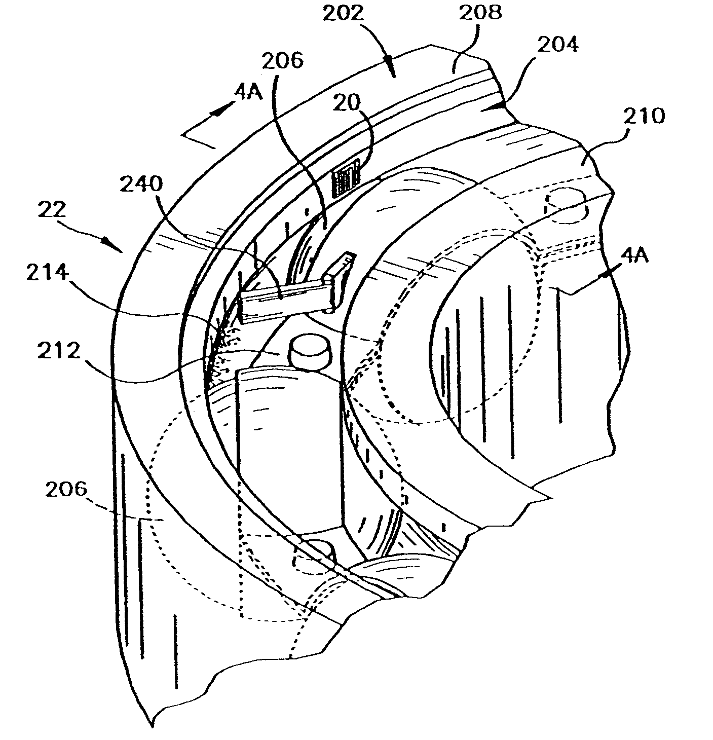
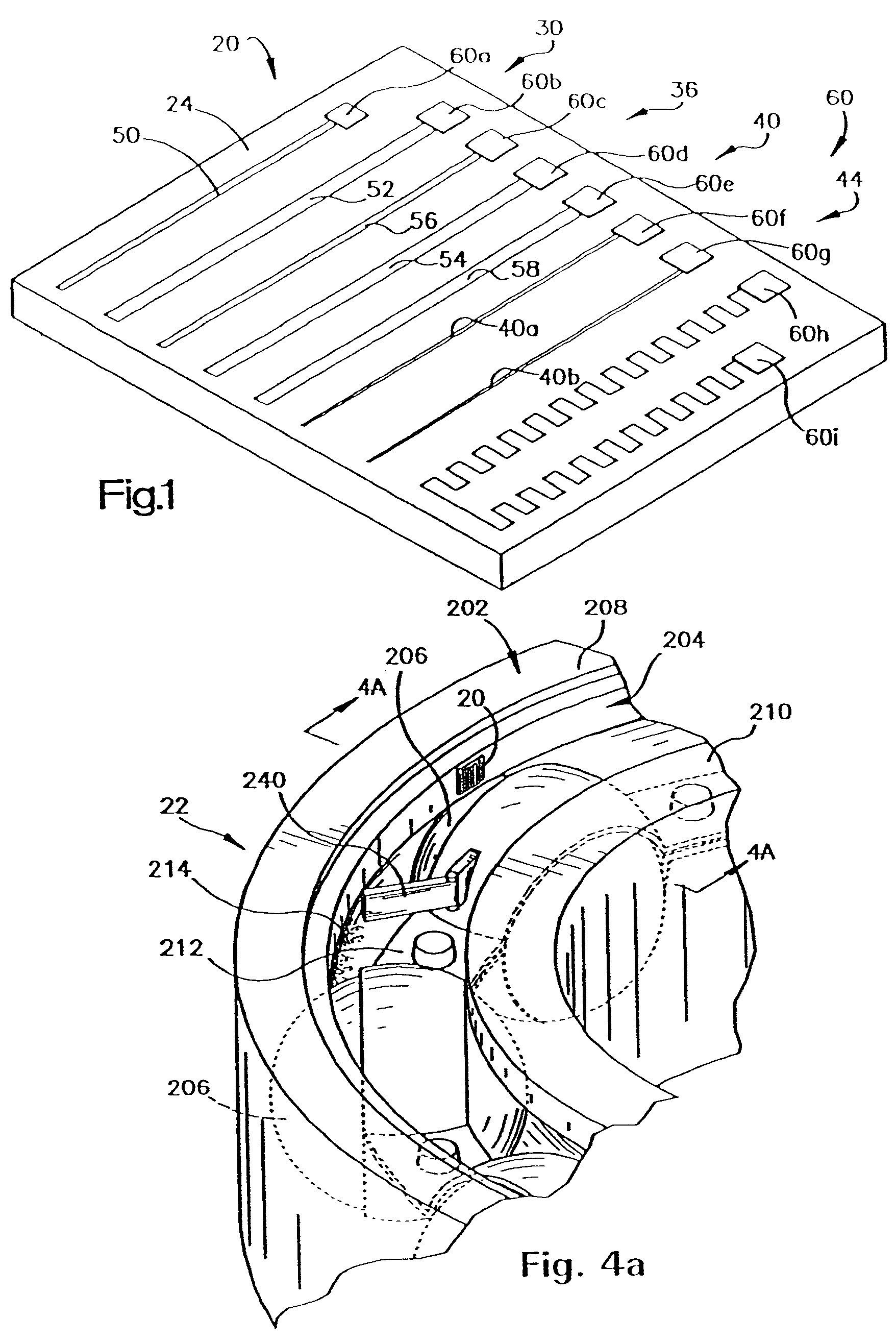
[0031]Referring now to the drawings in detail, and initially to FIG. 1, an exemplary lubrication-sensing device 20 is shown in perspective view. According to the present invention, the lubrication-sensing device 20 is integrated into a bearing 22 (FIGS. 4a, 4b and 5-13). This bearing-sensor integration allows in situ lubrication readings to be obtained at a substantially high data sampling rate whereby accurate up-to-date, real-time, continuous data analysis of lubrication health may be provided. In this manner, lubrication maintenance can be scheduled to correspond with the state of the lubrication and / or the processed data can be compiled for trend analysis and forecasting. Lubrication maintenance may be reliably scheduled based on the projected future state of the bearing lubricant. Performing maintenance based on projected future state of the lubricant enables industries to implement effective condition based maintenance programs.

[0032]Althoug...


PUM


Abstract

A system and methodology is provided for dynamically adjusting fluids that operate as a lubricant in a machine. The system includes a control module having a processor and one or more sensors providing data to the processor in situ with the machine, wherein the processor employs the data to monitor the fluid. One or more inputs are provided to receive a plurality of additives that are associated with the fluid, wherein actuators are employed by the processor to dispense the additives to the fluid. The processor dispenses the fluid based upon one or more parameters of the fluid.

Description

CROSS-REFERENCE TO RELATED APPLICATIONS[0001]This application is a divisional of U.S. patent application Ser. No. 11 / 041,317, filed Jan. 24, 2005, now U.S. Pat. No. 7,134,323, entitled, “SYSTEM AND METHOD FOR DYNAMIC LUBRICATION ADJUSTMENT FOR A LUBRICATION ANALYSIS SYSTEM,” which is a continuation of U.S. patent application Ser. No. 10 / 370,866, filed Feb. 20, 2003, now U.S. Pat. No. 6,877,360, entitled, “SYSTEM AND METHOD FOR DYNAMIC LUBRICATION ADJUSTMENT FOR A LUBRICATION ANALYSIS SYSTEM,” which is a continuation of U.S. patent application Ser. No. 10 / 036,154, filed Oct. 22, 2001, now U.S. Pat. No. 6,546,785, entitled, “SYSTEM AND METHOD FOR DYNAMIC LUBRICATION ADJUSTMENT FOR A LUBRICATION ANALYSIS SYSTEM,” which is a Continuation-in-Part of U.S. patent application Ser. No. 09 / 257,680, filed Feb. 25, 1999, now U.S. Pat. No. 6,324,899, entitled, “BEARING SENSOR INTEGRATION FOR A LUBRICATION ANALYSIS SYSTEM,” which is a Continuation-in-Part of U.S. patent application Ser. No. 09 / 05...

Claims


Application Information

Patent Timeline
IPC IPC(8): F01M11/10F01M11/12G01N33/30F16C19/52G01N11/16G01N29/02G01N33/28
CPCF16C19/52G01N11/16G01N29/022G01N33/2888G01N33/30F16C41/008F16N2250/30F16N2250/36F16N2260/18F16N2270/52F16N2270/54F16N2270/56G01N2291/0226G01N2291/0256G01N2291/02818G01N2291/106
Inventor DISCENZO, FREDERICK M.
Owner ROCKWELL AUTOMATION TECH
Why Eureka
Try Eureka