Device for mechanical weight bearing indication with load range capability

a technology of mechanical weight bearings and indicators, applied in the direction of force/torque/work measurement apparatuses, instruments, applications, etc., can solve the problems of not applying any weight, causing being almost as detrimental to the effect of further damage or pain, so as to achieve less attention, simple design, and rugged construction

Inactive Publication Date: 2009-02-24
RENESSELAER POLYTECHNIC INST
View PDF13 Cites 22 Cited by
  • Summary
  • Abstract
  • Description
  • Claims
  • Application Information

AI Technical Summary

Benefits of technology

[0019]Another advantage of the invention is that the feedback signal, including the audible sound, is perceptible, generally only by the patient so that less attention is drawn to the patient or the patient's condition as compared to other devices.
[0020]In addition to its therapeutic value, the present invention is also a simple device for use in athletics, physical therapy, gait analysis and the like, wherever a set force limit is desirable or not desirable for applying between a part of the body and another surface.
[0021]Accordingly an object of the present invention is to provide a purely mechanical load bearing indicator for producing signals to a user when the user applies more than selected amounts of load between an extremity being used and a surface, comprising a base plate adapted to establish a frame of reference with the surface, a load plate mounted for movement toward and away from the base plate and adapted to receive loads from the user's extremity, and at least two snap domes mechanically engaged between the base plate and the load plate for generating two signals when more than two different respective loads are applied to the load plate by the extremity.
[0022]Another object of the invention is to provide the domes in series or as a dual dome containing both, as one or more stacks of domes which individually collapse under incremental loads which are added together to form the selected lower and higher loads. Another object of the present invention is to provide a mechanical weight bearing indicator which is simple in design, rugged in construction and economical to manufacture.

Problems solved by technology

As a result, most patients do not apply any weight or apply insufficient weight to the injured lower extremity in fear of causing further damage or pain.
The application of weight is necessary, however, for proper recovery and not applying any weight is almost as detrimental as applying too much weight.

Method used


Image

  • Device for mechanical weight bearing indication with load range capability
  • Device for mechanical weight bearing indication with load range capability
  • Device for mechanical weight bearing indication with load range capability

Examples


third embodiment

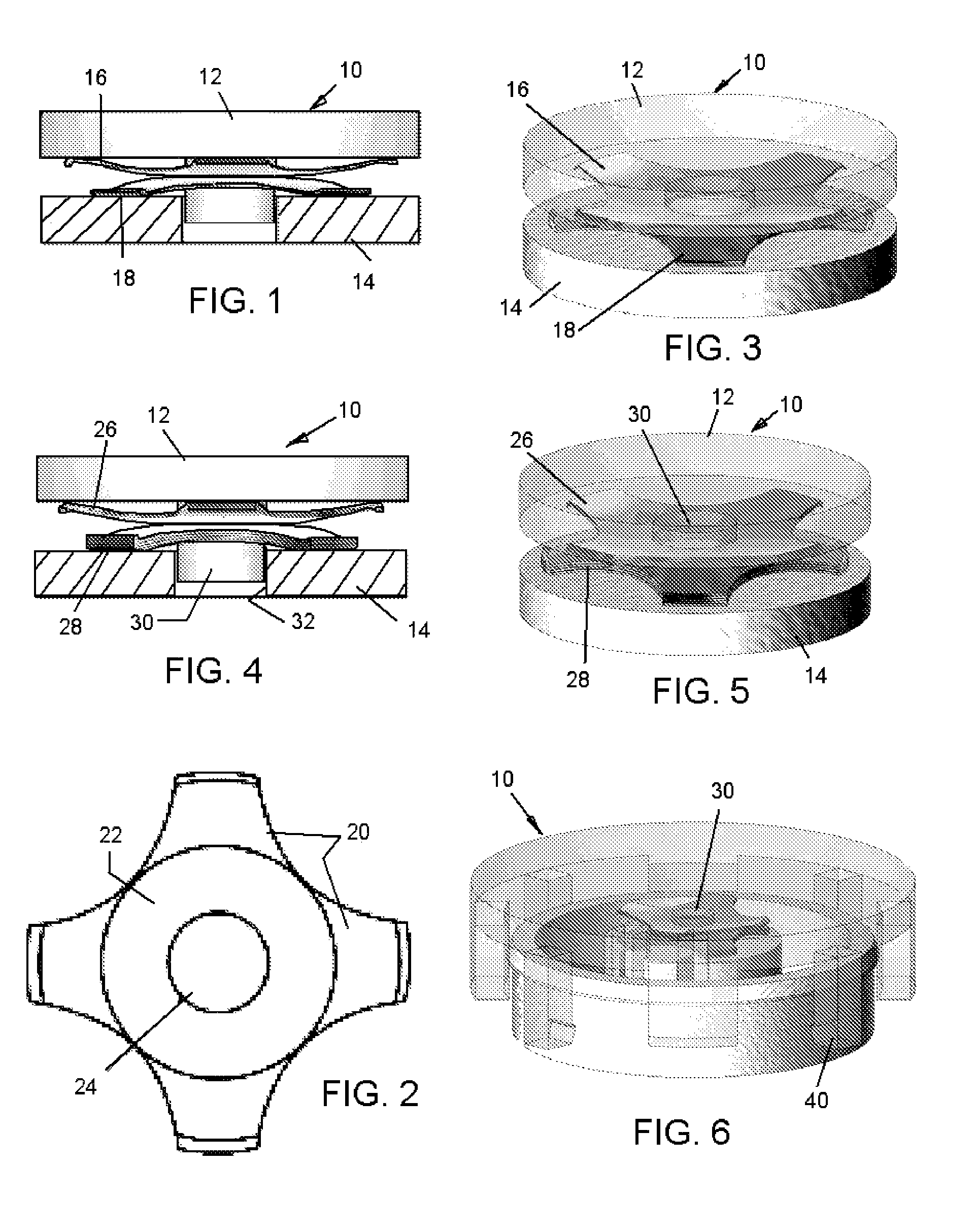
[0061]the invention is illustrated in FIG. 6.

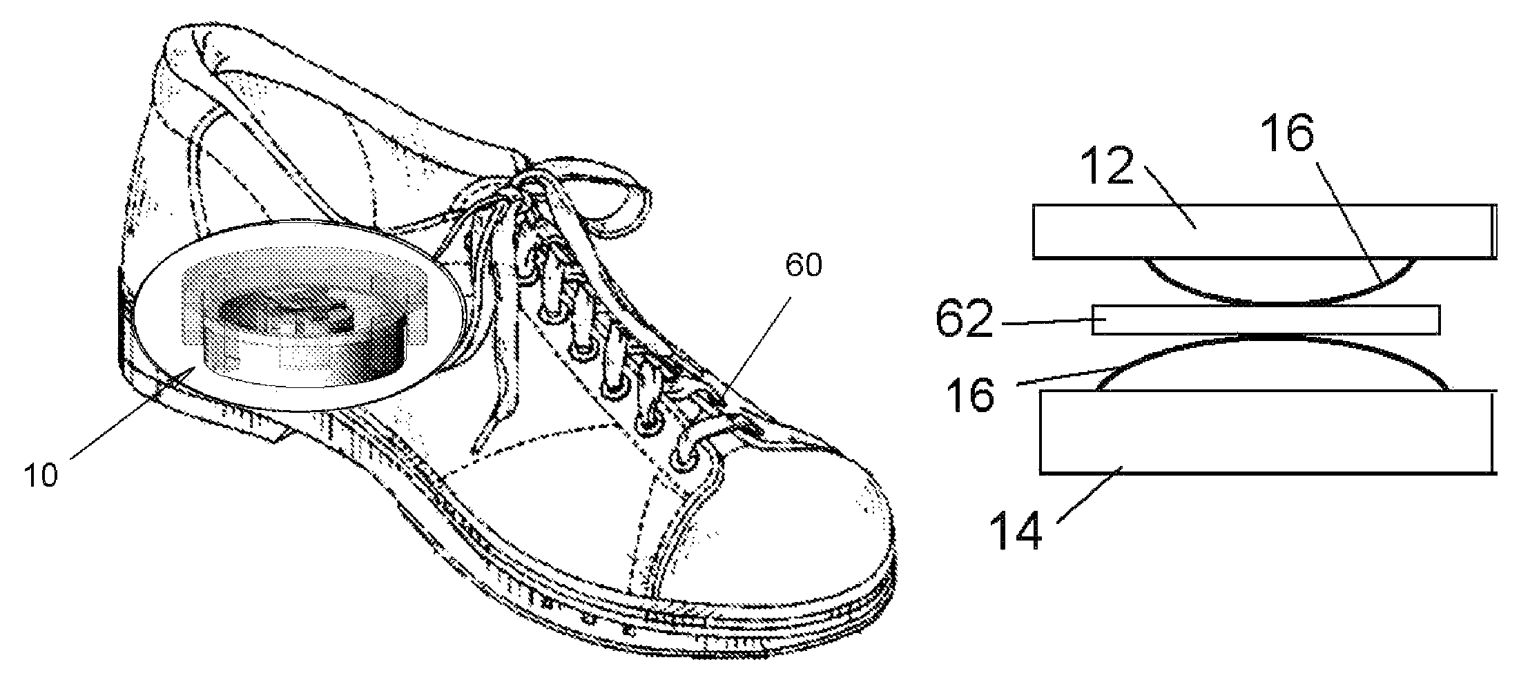
[0062]It is noted that in a preferred form of the invention as shown in all of FIGS. 1, 3, 4, 5 and 6, the load transfer plate 12 has a center post 30 rigidly attached to the upper plate 14 (shown) or the upper plate 12 to retain the lateral positions of both dome stacks. All snap domes in these embodiments will have the central hole 24 (see FIG. 2). This post 30 rides in a hole 32 provided in the base plate 14 as the plates are force toward each other during each step the user takes. The load transfer plate 12 will also be covered with a low-durometer foam or polymeric gel material, if needed.

[0063]Assembly of all the components is facilitated by a snap fit between the load transfer plate 12 which, as shown in FIG. 6 has multiple, e.g. four, retaining legs 40 that are evenly spaced around the plate 12 and embrace the base plate 14. Four support tabs guide the load transfer plate.

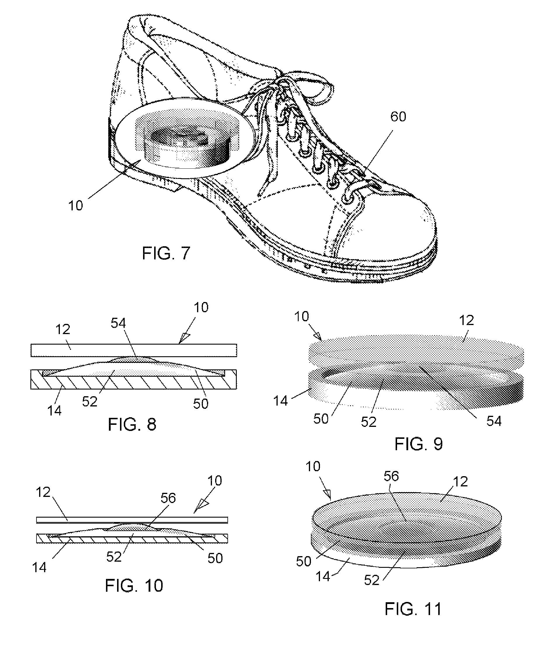
[0064]FIG. 7 shows the embodiment of FIG. 6 installed in th...

fourth embodiment

[0065]the invention is illustrated in FIGS. 8 and 9 and uses low and high load domes 54 and 52 respectively, that are integrated into a single component 50 shown in the un-loaded position in FIG. 8. This dual snap dome is custom manufactured and includes a large diameter dome 52 that is in contact with the base plate 14, and a smaller snap dome 54 whose apex is in contact with the load transfer plate 10. When the lower desired load is reached, part 54 will buckle signaling the wearer via an audible click and a tactile sensation under the foot. When the upper desired load is reached, part 52 will buckle with the smaller diameter part 54 still in its compressed condition and, again, signaling the wearer with a lower-pitched audible click and tactile sensation under the foot.

[0066]A fifth embodiment of the invention is illustrated in FIGS. 10 and 11, which is very similar to the fourth embodiment except that the smaller diameter dome 56 is a separate part that nests in a recess at the ...


PUM

PropertyMeasurementUnit
diameteraaaaaaaaaa
heightaaaaaaaaaa
mechanicalaaaaaaaaaa

Abstract

A mechanical load bearing indicator producing signals to a user when the user applies more than selected amounts of load between an extremity of the use and a surface. The indicator has a base plate adapted to establish a frame of reference with the surface, a load plate mounted for movement toward and away from the base plate and adapted to receive loads from the user's extremity, and at least two snap domes mechanically engaged between the base plate and the load plate for generating two signals when more than two different respective loads are applied to the load plate by the extremity. The domes are either in series between the plates or are together in a dual dome containing both, or are one or more stacks of domes which individually collapse under incremental loads which are added together to form the selected lower and higher loads.

Description

FIELD AND BACKGROUND OF THE INVENTION[0001]The present invention relates, in general, to force indicators for medical or biological uses, and in particular, to a new and useful weight bearing indicator which is purely mechanical yet provides an unambiguous message, both tactile and audible, to a person wearing the indicator when two different amounts of force between the person's foot and the ground have been exceeded.[0002]Following orthopedic surgery or injury to the lower extremities, patients are encouraged to gradually bear weight on their limb, but are warned not to exert more than a certain limited amount of force on the injured extremity.[0003]As a result, most patients do not apply any weight or apply insufficient weight to the injured lower extremity in fear of causing further damage or pain. The application of weight is necessary, however, for proper recovery and not applying any weight is almost as detrimental as applying too much weight. A survey was conducted at Albany...

Claims


Application Information

Patent Timeline
Patent Type & Authority Patents(United States)
IPC IPC(8): G01L1/04A61B5/00G01L1/06
CPCG01L1/04G01L5/06
Inventor WALCZYK, DANIEL F.BORNHOFT, STEPHEN
Owner RENESSELAER POLYTECHNIC INST
Why Eureka
Try Eureka