Underground pipe inspection device and method

a technology for underground pipes and inspection devices, applied in mechanical devices, instruments, magnetic variables, etc., can solve problems such as the inability to use “pigs” or robots for inspection, and achieve the effect of uniform pipe coverag

Inactive Publication Date: 2009-02-24
GAS TECH INST
View PDF10 Cites 43 Cited by
  • Summary
  • Abstract
  • Description
  • Claims
  • Application Information

AI Technical Summary

Benefits of technology

[0009]It is yet another object of this invention to provide a method and apparatus for inspecting the walls of underground pipes which provides uniform inspection of the walls during axial traversal of the pipe.
[0010]These and other objects of this invention are addressed by an apparatus comprising a circular planar platform and at least one lever arm pivotably attached to the platform and having a free end to which may be attached an inspection device, such as a sensor. The lever arm is attached to the platform in an orientation providing a direction of pivoting substantially parallel to the plane of the platform. This device supports and places inspection equipment in contact with the inside diameter of any underground pipeline infrastructure encountered during the inspection process. The device enables the expansion and contraction of the inspection equipment to accommodate a diameter change three times the smallest inspected diameter. The device holds the sensing equipment at a constant angle to the pipeline for all diameters and provides uniform coverage of the pipe by maintaining a constantly changing, equidistant arc length between the sensing equipment for any pipe diameter. The device of this invention provides for the support and / or centering of any number of devices within the pipeline. Used in conjunction with the currently available inspection technologies, and currently available propulsion methods, this device is capable of inspecting “unpiggable” pipelines.

Problems solved by technology

However, there exist numerous obstructions such as valves, offsets, bends, and reductions in diameter within the pipeline that can prevent traversal of the “pig” through the pipeline, thereby precluding the use of “pigs” or robots for inspection of those sections of pipeline having these obstructions.

Method used


Image

  • Underground pipe inspection device and method
  • Underground pipe inspection device and method
  • Underground pipe inspection device and method

Examples


Embodiment Construction

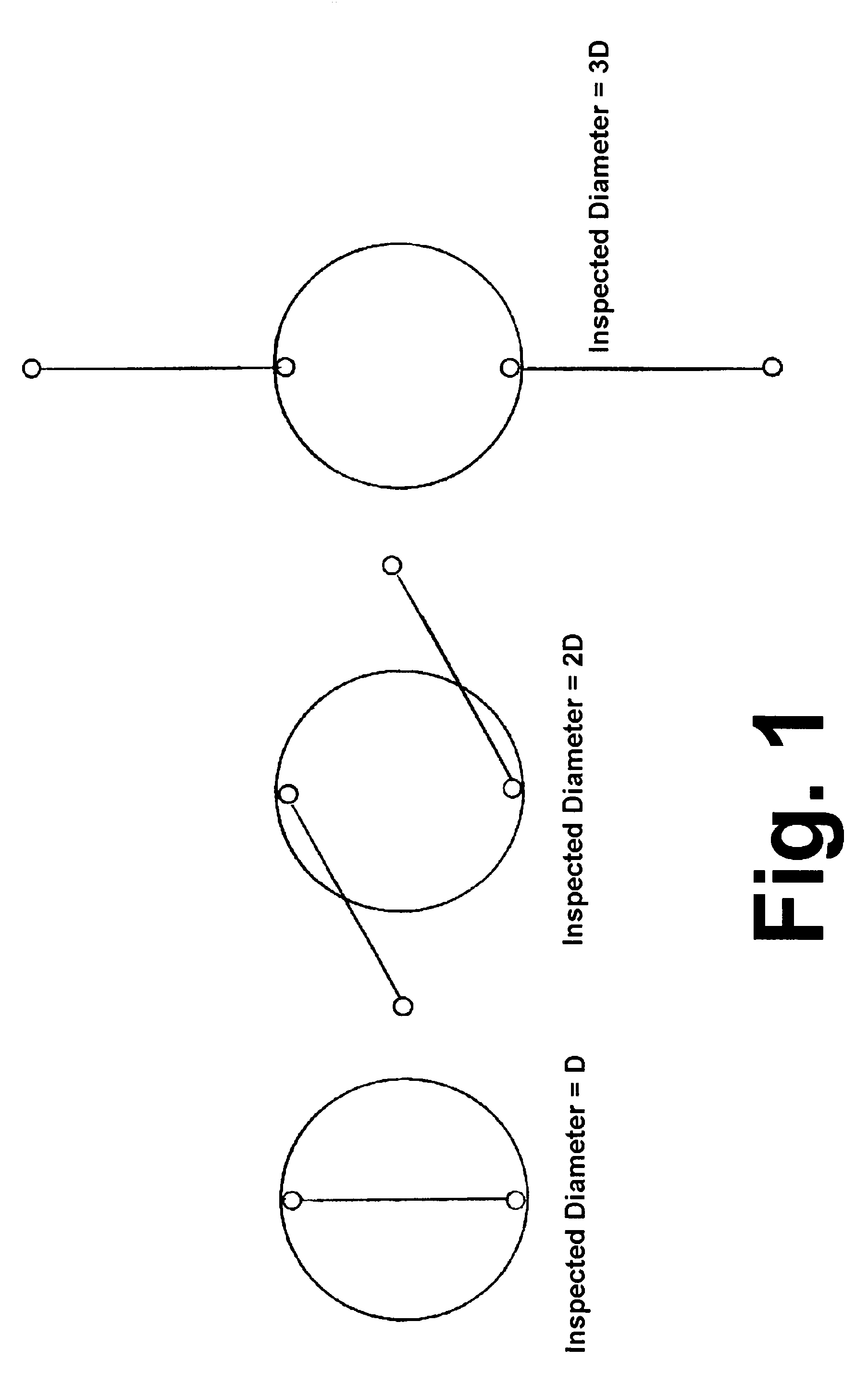
[0020]The fundamental principle of this invention is that the entire diameter of a device can be used as a lever arm for the sensors employed in the inspection of the inside of a pipeline. As the lever arms swing out from the pivot point, the device can accommodate different pipe diameters. The maximum pipe diameter that can be inspected is limited by the length of the lever arm of the device. When the lever arms are rotated a full 180° from the fully closed or contracted position to the fully open or extended position, the maximum diameter, which optimally will be three times the diameter of the device, is reached.

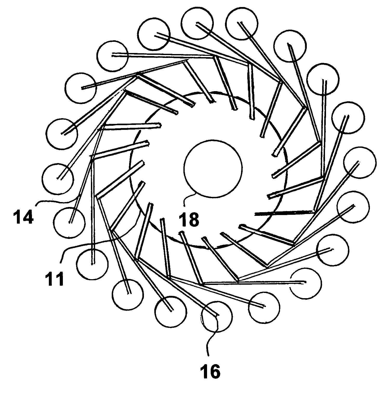
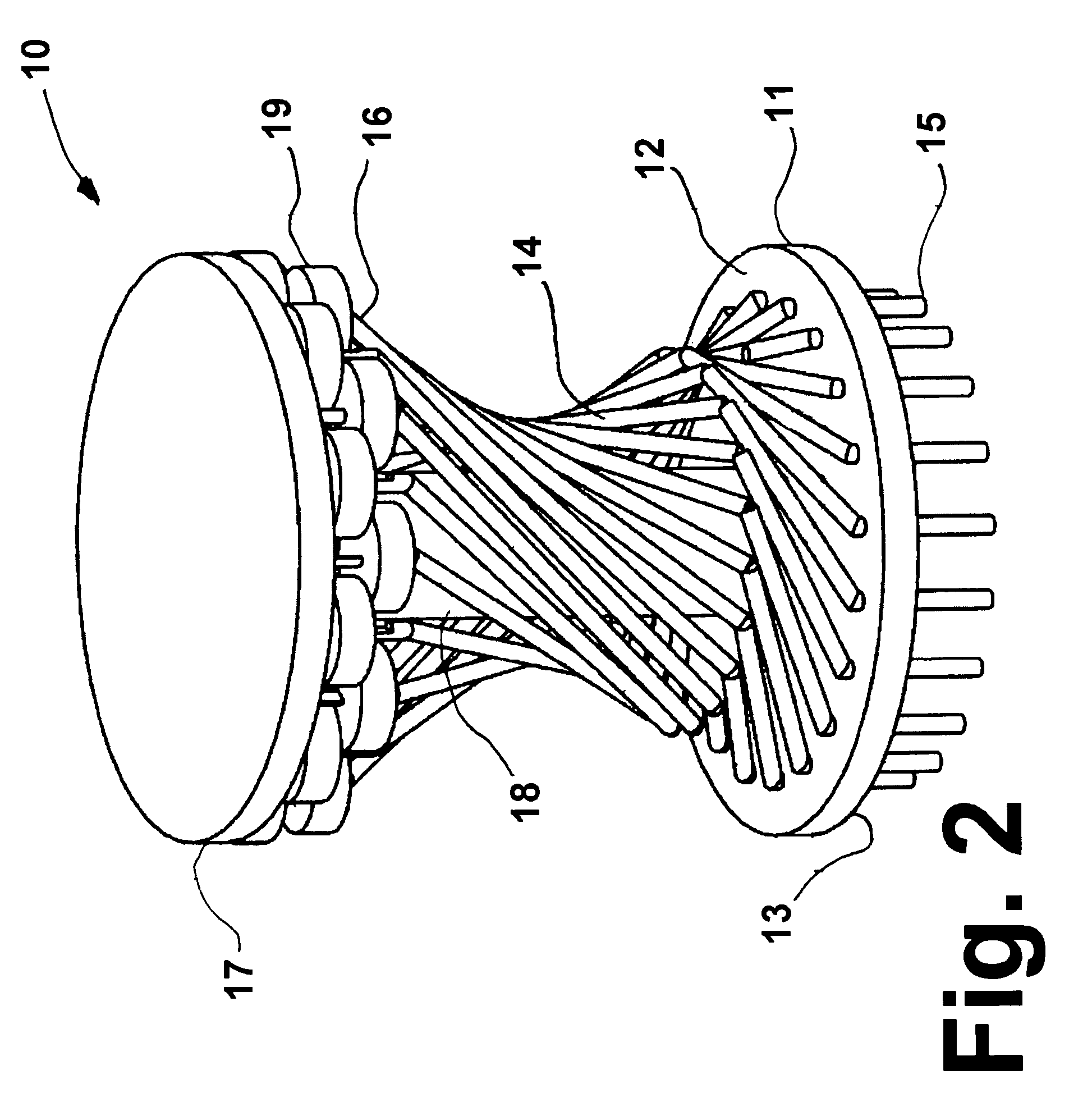
[0021]The schematic of the concept of this invention is shown in FIG. 1. In 2-dimensional space, the device is limited to a single lever arm. However, in 3-dimensional space, it is possible to increase the number of lever arms because they can now be stacked on top of each other as shown in FIG. 2. The 3-dimensional limit of the number of lever arms in accordance with the...


PUM


Abstract

A method and apparatus for inspecting the walls of an underground pipe from inside the pipe in which an inspection apparatus having a circular planar platform having a plurality of lever arms having one end pivotably attached to one side of the platform, having a pipe inspection device connected to an opposite end, and having a system for pivoting the lever arms is inserted into the underground pipe, with the inspection apparatus oriented with the planar platform disposed perpendicular to the pipe axis. The plurality of lever arms are pivoted toward the inside wall of the pipe, contacting the inside wall with each inspection device as the apparatus is conveyed along a length of the underground pipe.

Description

CROSS REFERENCE TO RELATED APPLICATION[0001]This application claims the benefit of provisional U.S. patent application Ser. No. 60 / 693,326 filed 23 Jun. 2005.[0002]The U.S. Government has a paid-up license in this invention and the right in limited circumstances to require the patent owner to license others on reasonable terms as provided for by the terms of DOE Cooperative Agreement No. DE-FC26-04NT42266 awarded by the U.S. Department of Energy.BACKGROUND OF THE INVENTION[0003]This invention relates to a method and apparatus for inspecting the inside walls of underground pipes. More particularly, this invention relates to a method and apparatus for inspecting the entire wall of underground pipes in which the inspection devices for assessing the physical and structural integrity of the walls are conveyed through the pipe.[0004]Utilities are responsible for the regular maintenance and integrity of their underground infrastructure. They usually rely on “smart pigs” or robots for the i...

Claims


Application Information

Patent Timeline
Patent Type & Authority Patents(United States)
IPC IPC(8): G01H3/00G01M99/00
CPCF16L55/40F17D5/02
Inventor GERMATA, DANIEL THOMAS
Owner GAS TECH INST
Why Eureka
Try Eureka