Method for operating an internal combustion engine

a technology of internal combustion engine and fuel injection, which is applied in the direction of machines/engines, relays, electric control, etc., can solve the problems of oversized reload circuits and booster capacitors for normal operation, and achieve the effect of increasing current intensity

Inactive Publication Date: 2009-03-03
ROBERT BOSCH GMBH
View PDF16 Cites 11 Cited by
  • Summary
  • Abstract
  • Description
  • Claims
  • Application Information

AI Technical Summary

Benefits of technology

[0006]This problem is solved using a method for operating an internal combustion engine with a fuel injector that is opened and closed electrically. A booster capacitor serves to increase the current intensity when the fuel injector is opened. The current profile of the booster current is switched—in certain operating states of the internal combustion engine—from a standard value to an increased value and / or to a longer duration and, when the certain operating state ends, the current profile of the booster current is reset to the standard value and the standard duration. During a starting procedure of the internal combustion engine and / or when fuel injection is resumed after an overrun condition, the current profile of the booster current is preferably switched from the standard value to the extended booster phase and, when the starting procedure ends and after a few injections have been carried out after fuel injection has been restored after an overrun condition, the current profile of the booster current is reset to the standard value or the standard duration of the booster phase. The current profile of the booster current is preferably switched to an overall longer duration using multiple booster pulses, i.e., by repeatedly switching on the booster current for a short period each time.
[0007]The opening pressure of the high pressure injectors is increased by changing the booster current for the two cases described above. The change in the booster current must be restored quickly when the fuel pressure falls, to prevent a deep discharge of the booster capacitor. Since only a few fuel injections are carried out with the changed booster current, the discharge of the booster capacitor is minimal, which ensures that further fuel injections can be carried out. A further advantage is the fact that the reload circuit and the booster capacitor can be sized for normal operation. It is not necessary to oversize them for the hot start and resumption after overrun fuel cutoff. Furthermore, the opening force of the high pressure injector can be increased (e.g., by increasing the static flow rate of the valve) without changing the hardware. By using a greater static flow rate, a supercharged version of an engine series can be served, for example, and / or the power loss in the electronic control unit caused, e.g., by a shortening of the fuel injection window, can be reduced. When the static flow rate is greater, the start-up behavior at low temperatures is also improved.
[0012]Therefore, as soon as the system pressure falls below the pressure threshold again, or as soon as the number of fuel injections carried out with the changed current profile falls exceeds a certain threshold, the current profile is quickly reset to the original, lower level. This therefore prevents the booster capacitor from becoming deeply discharged, which could result in fuel injection failures.

Problems solved by technology

This means that the reload circuit and the booster capacitor are oversized for normal operation.

Method used


Image

  • Method for operating an internal combustion engine
  • Method for operating an internal combustion engine
  • Method for operating an internal combustion engine

Examples


Embodiment Construction

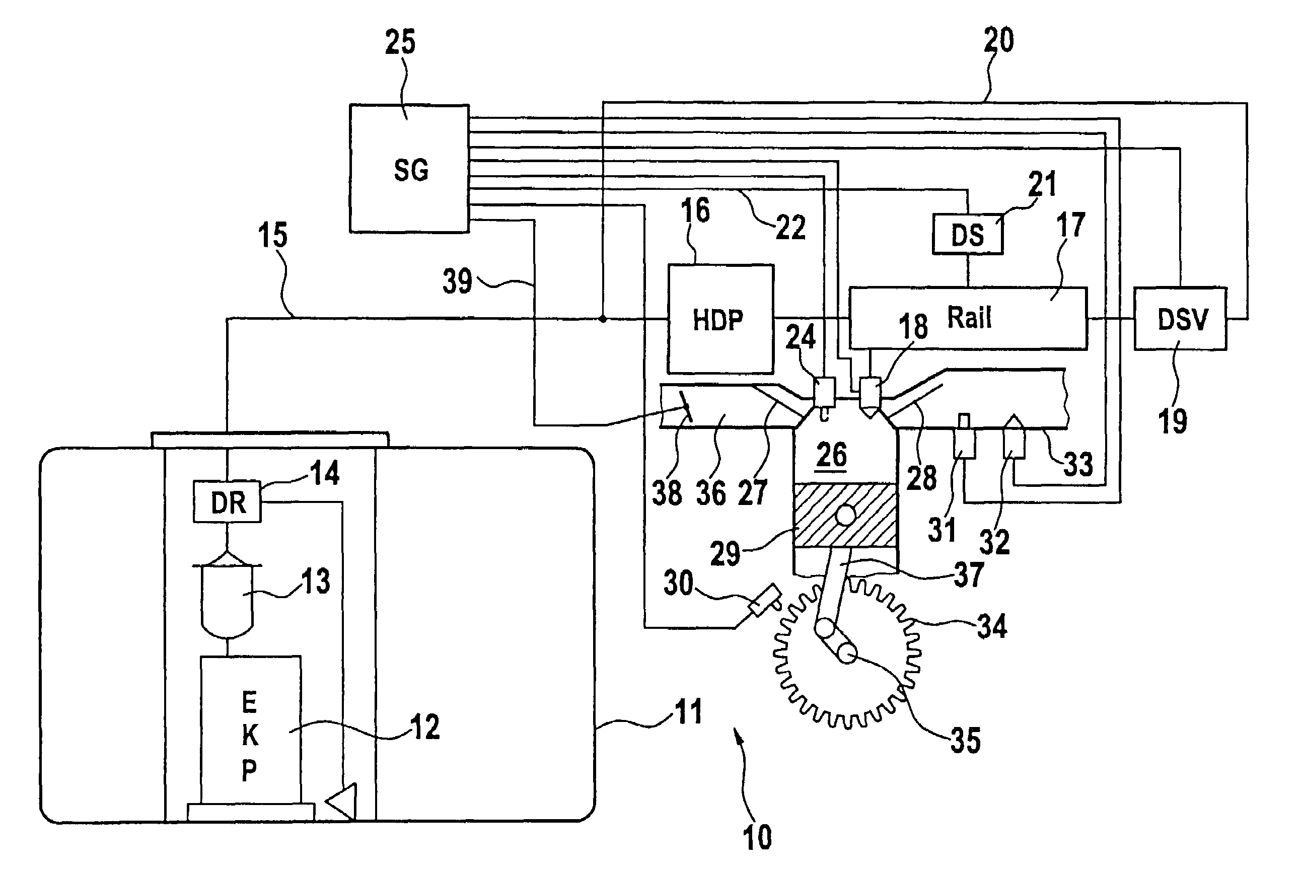
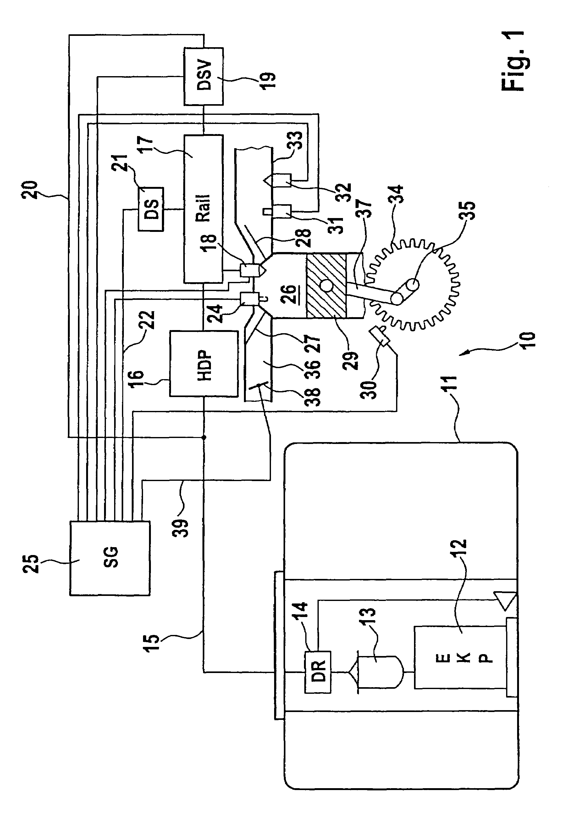
[0017]FIG. 1 shows a schematic depiction of a cylinder of an internal combustion engine with associated components of the fuel supply system. The figure shows an internal combustion engine with direct injection (gasoline direct injection, DI) with a fuel tank 11, on which electric fuel pump (EKP) 12, a fuel filter 13 and a low pressure regulator 14 are located. From fuel tank 11, a fuel line 15 leads to a high pressure pump 16. Storage chamber 17 is connected to high pressure pump 16. Fuel injectors 18 are located on storage chamber 17, fuel injectors 18 preferably being assigned directly to combustion chambers 26 of the internal combustion engine. With internal combustion engines with direct injection, at least one fuel injector 18 is assigned to each combustion chamber 26, although a plurality of fuel injectors 18 can also be provided for each combustion chamber 26. The fuel is pumped by electric fuel pump 12 out of fuel tank 11 through fuel filter 13 and fuel line 15 to high pres...


PUM


Abstract

With a method for operating an internal combustion engine with a fuel injector (18) that is opened and closed electrically, a booster capacitor (BK) serving to increase the current intensity when the fuel injector (18) is opened, reliable fuel injection is ensured, even in extreme cases, such as resumption of fuel injection after an overrun condition, and in a starting procedure after a shutoff phase that is accompanied by an increase in pressure in the high pressure fuel system due to the fuel heating up, when booster capacitors are used that were designed for normal operation, by switching the current profile in certain operating states of the internal combustion engine from a standard value to an increased value and / or to a longer duration and, when the certain operating state ends, by resetting it to the standard value and the standard duration.

Description

CROSS-REFERENCE[0001]The invention described and claimed hereinbelow is also described in PCT / EP 2005 / 056033, filed on Nov. 17, 2005 and DE 102004063079.8, filed Dec. 28, 2004. This German Patent Application, whose subject matter is incorporated here by reference, provides the basis for a claim of priority of invention under 35 U.S.C. 119 (a)-(d).BACKGROUND OF THE INVENTION[0002]The present invention relates to an internal combustion engine and a method for operating it.[0003]To open an inwardly opening, high-pressure fuel injection solenoid valve used with gasoline direct injection, the high system pressure makes it necessary to include a booster phase, in which the current flowing through the high pressure injector increases to values such as 12 A. The high current is generated by connecting the high pressure injector to a booster capacitor that stores energy with a voltage of, e.g., 65 V, and delivers it to the high pressure injector during the booster phase. The energy withdrawn...

Claims


Application Information

Patent Timeline
Patent Type & Authority Patents(United States)
IPC IPC(8): F02M51/00
CPCF02D41/20F02D41/065F02D41/126F02D41/3809F02D2041/2003F02D2041/2006F02D2041/2017F02D2041/389F02D2200/0602
Inventor KEMMER, HELERSON
Owner ROBERT BOSCH GMBH
Why Eureka
Try Eureka