Automatic liquid barrier system

a liquid barrier and automatic technology, applied in the direction of shutters/movable grilles, marine site engineering, construction, etc., can solve the problems of not being able to construct a temporary barrier in time, not being able to run on materials,

Inactive Publication Date: 2009-03-03
COHEN MAURICE
View PDF7 Cites 12 Cited by
  • Summary
  • Abstract
  • Description
  • Claims
  • Application Information

AI Technical Summary

Benefits of technology

[0009]As stated above, the float assembly comprises a float which is positionable within said float housing relative to a liquid level therein, and the barrier is interconnected to at least a portion of the float assembly and moveable therewith. As such, the barrier is automatically deployed into the sealing engagement with the seal member along the portion of the

Problems solved by technology

Yet another problem with reliance upon such a temporary barrier in response to an impending flood condition is that there is often a “run” on materials, i.e., sand and sacks needed to make sandbags, or other materials necessary to construct a temporary dike or levee.
Even in the event the necessary materials are readily available, the construction of one or more temporary barriers is labor intensive and, thus, time consuming, such that it may not be feasible to construct a temporary barr

Method used


Image

  • Automatic liquid barrier system
  • Automatic liquid barrier system
  • Automatic liquid barrier system

Examples


Embodiment Construction

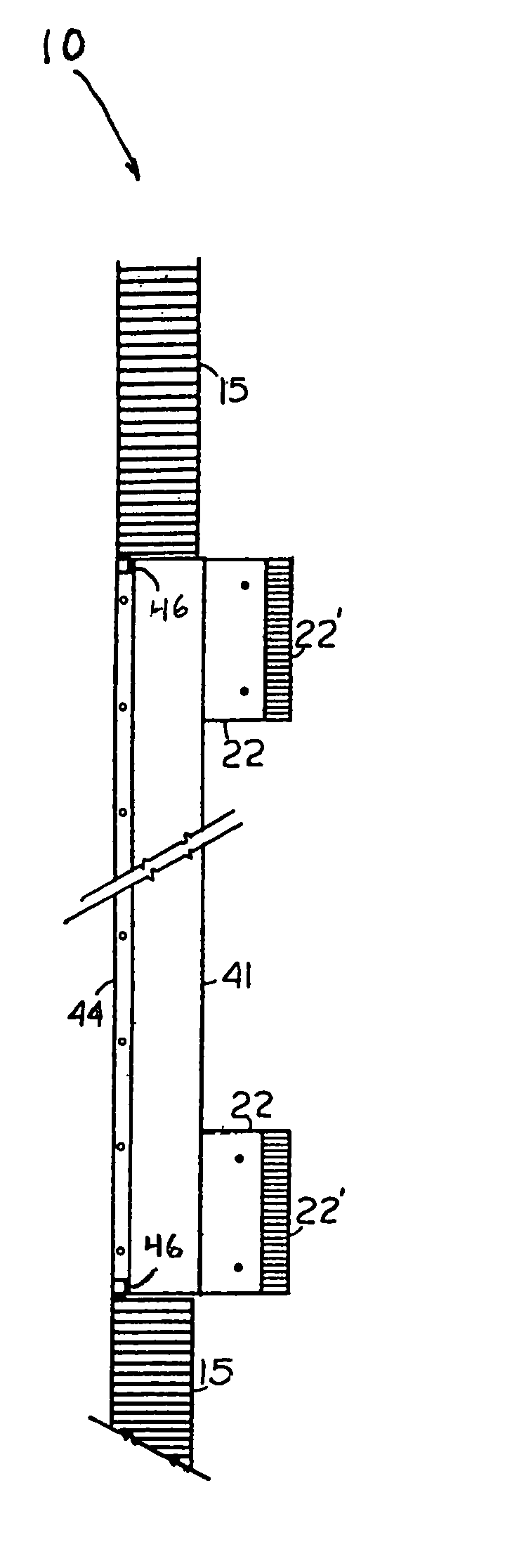
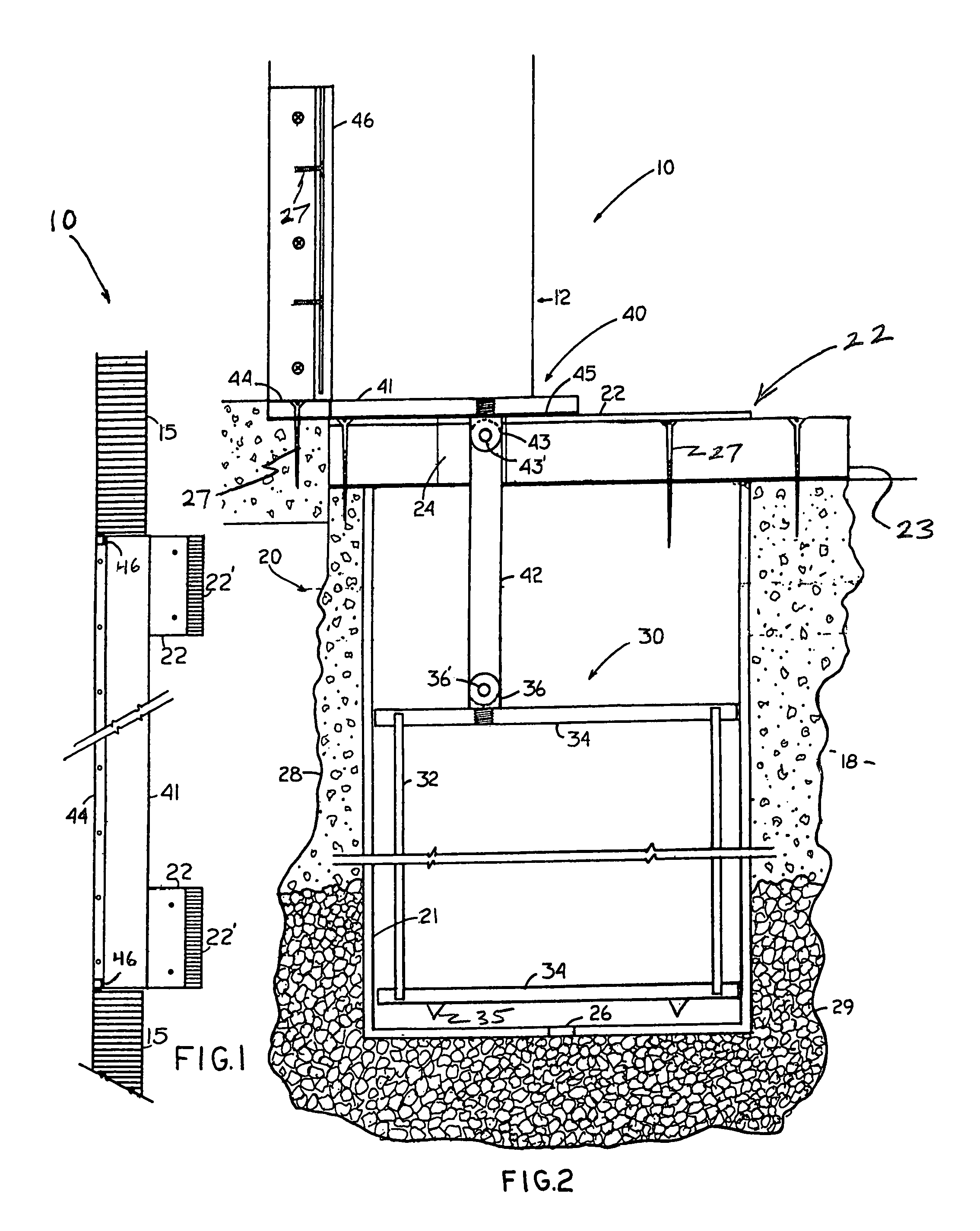
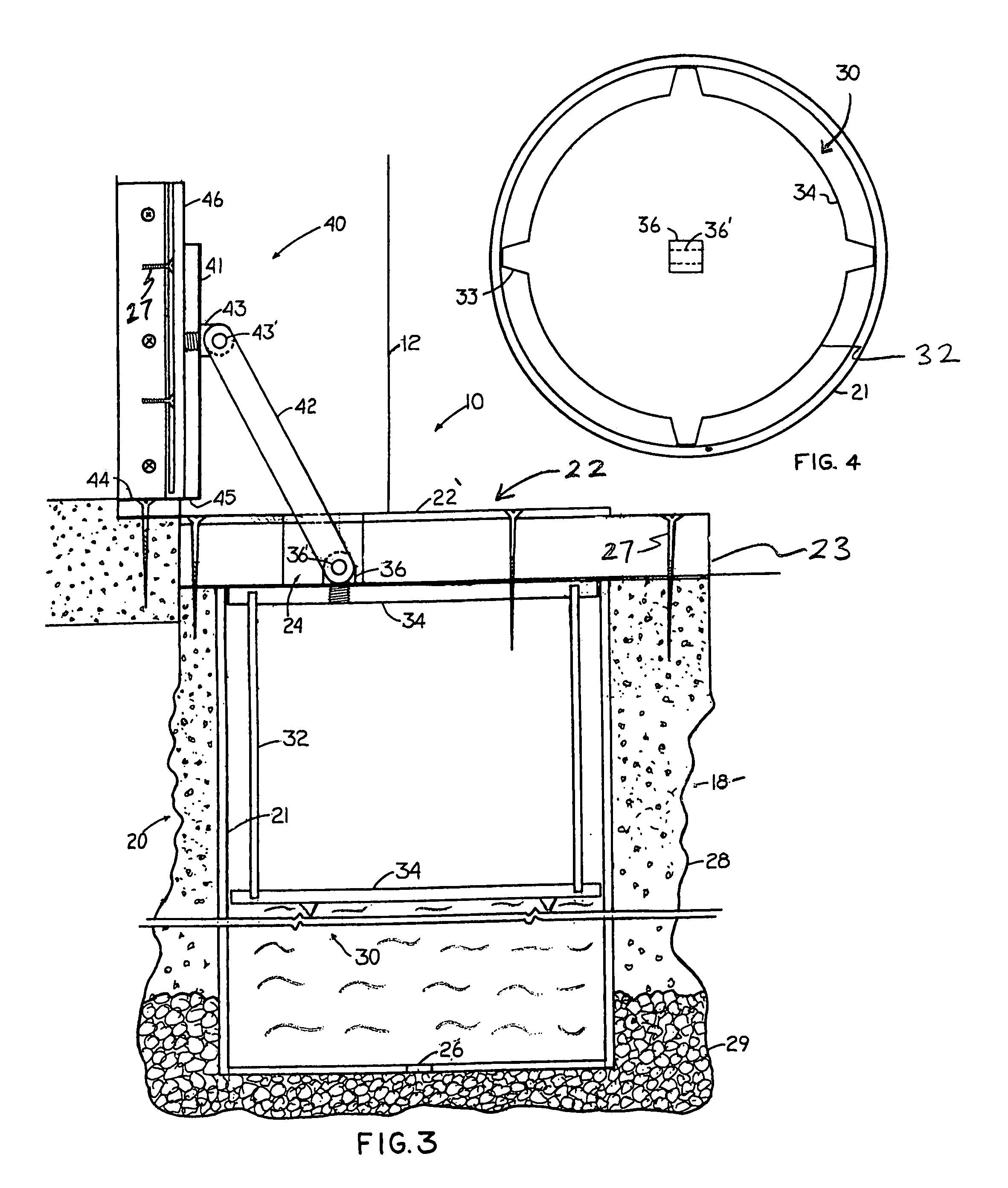
[0021]The present disclosure is directed to an automatic liquid barrier system for an accessway, as shown at 10 throughout the drawings. More in particular, the system 10 in accordance with the present disclosure is structured to prevent a flow of liquid, such as rain or flood water, into a structure via an accessway such as a door, window, or other opening through an external wall of the structure. Further, the present disclosure contemplates structures such as residential homes or apartments, office buildings, commercial properties, including for example, store fronts, warehouses, etc., as well as various industrial and manufacturing facilities. In fact, the system 10 is versatile enough to provide an automatic liquid barrier system 10 to protect any of the aforementioned structured, as well as other structures not specifically discussed herein.

[0022]To begin, the automatic liquid barrier system 10 includes a float housing assembly, as shown at 20 throughout the figures, installed...


PUM


Abstract

A liquid barrier system automatically deploys when a predetermined liquid level is attained, thereby preventing water or other liquid from entering a structure through an accessway, and automatically retracts when the liquid level recedes. The liquid barrier system includes a float housing assembly installed substantially below grade and adjacent an accessway to a structure. The system also includes a float assembly having a float which is positionable within a float housing relative to a liquid level in the housing. A barrier assembly includes a barrier interconnected to the float, and one or more seal members disposed along a periphery of an accessway. In a high water event, the float rises with the liquid level in the float housing thus causing the barrier to automatically deploy into a sealing engagement with the seal member(s) along the periphery of the accessway, thereby preventing the entry of fluid into the structure.

Description

BACKGROUND[0001]The present disclosure is directed to a liquid barrier system structured to automatically deploy in high water conditions, so as to prevent water from entering a structure through an accessway, and to automatically retract when the high water condition subsides. The system is structured to be installed in conjunction with a new structure, or an existing structure may be retrofitted to incorporate the inventive system.DESCRIPTION OF THE ART[0002]Impending flood conditions may result from extended periods of rainfall which saturates or supersaturates the water table and / or cause rivers to crest and breach their banks, or from sudden torrential downpours as are often associated with tropical weather fronts which have the same impact over significantly shorter timeframes. In either case, a common response to imminent flood conditions is to construct one or more temporary barrier(s) to protect homes, stores, offices, and other structures from rising flood waters in order ...

Claims


Application Information

Patent Timeline
IPC IPC(8): E02B7/50
CPCE06B9/04E06B2009/007
Inventor COHEN, MAURICE
Owner COHEN MAURICE
Why Eureka
Try Eureka