Flexible size adjustable filter element

a filter element and flexible technology, applied in the field of flexible or folding size adjustable filter elements, can solve the problems of reducing the mechanical and thermodynamic efficiency of the original equipment manufacturer's air conditioning system, affecting the efficiency of the mechanical and thermodynamic efficiency of the original equipment manufacturer, and the choice of the technician's little choi

Active Publication Date: 2009-03-03
BONDED FILTER
View PDF7 Cites 28 Cited by
  • Summary
  • Abstract
  • Description
  • Claims
  • Application Information

AI Technical Summary

Benefits of technology

[0010]The present invention overcomes the shortcomings of the prior art by providing a filter element that is partially fabricated on site wherein one or more wire frames are flexibly attached to each other end-to-end using flexible attachment means to form a structure substantially conforming to the dimensions of the original equipment manufacturer's filter housing. The flexible attachment means hold the wire frame members together without overlap. The wire frames when inserted into the filter housing provides the necessary structural support for a filter element and wire mesh. Because the wire frame members are flexibly attached, the assembled filter unit of the present invention can be inserted into the filter housing one frame at a time, with the frame sections yet to be inserted folded or directed off to one side, thus bypassing space restrictions that would prevent a full-sized filter unit with rigidly attached frame members, constructed in accordance with the prior art, from being removed or inserted.
[0013]In another exemplary embodiment, one or more end-caps are affixed to one or both ends of the filter element to protect the filter element from abrasion and wear during shipping, handling, and installation of the filter, and to protect the installer from injury. The end-cap may be made of any appropriate protective material, including, but not limited to, adhesive tape, cardboard, heavy paper, or plastic material. In yet another exemplary embodiment, the end-cap may contain printed material, such as text or pictures, which may include instructions for use, identifying labels or symbols, or the like.

Problems solved by technology

Over time, contaminants build up on the filter media, thus necessitating replacement of the filter element.
This system often leaves the technician with little choice but to stock every or most conceivable filter elements and to carry them from job site to job site.
In addition, replacement filter elements frequently allows significant contaminated airflow to circulate around the replaceable filter elements due to variations in tolerances between the replaceable filter elements and the original equipment manufacturers' channeled filter housing.
This condition also decreases the mechanical and thermodynamic efficiency of the original equipment manufacturer's air conditioning system.
Further, the standard cardboard superstructure employed to give rigidity to replacement filter elements may result in the rigidity deteriorating during high humidity conditions or rainstorms.
The replacement filter element may then be drawn out of the air conditioning system's channeled filter housing and into the air-moving fan, thus destroying the replaceable filter element's ability to filter.
Use of the cardboard superstructure also blinds a portion of the replaceable filter element and reduces the capacity of the filter element to capture and retain particulate matter.
And finally, use of cardboard superstructure requires the use of wood fiber and is not environmentally conservative.
Nevertheless, several problems still remain.
However, such equipment often is installed in such a manner where access to the filter housing is limited in space, so that a replacement air filter of the proper length cannot be inserted into the filter housing without moving the unit or neighboring equipment.
Furthermore, problems have been found with the ends of the filter element being exposed during shipping, assembly and insertion, resulting in damage to the filter element and injury to the individual doing the installation.

Method used


Image

  • Flexible size adjustable filter element
  • Flexible size adjustable filter element
  • Flexible size adjustable filter element

Examples


Embodiment Construction

[0028]Referring now to the numerous figures, wherein like references identify like elements of the invention, FIGS. 1 through 7 illustrate examples of the prior art as presented in Culwell, U.S. Pat. No. 6,152,980, and FIGS. 8 through 10 illustrate various exemplary embodiments of the present invention.

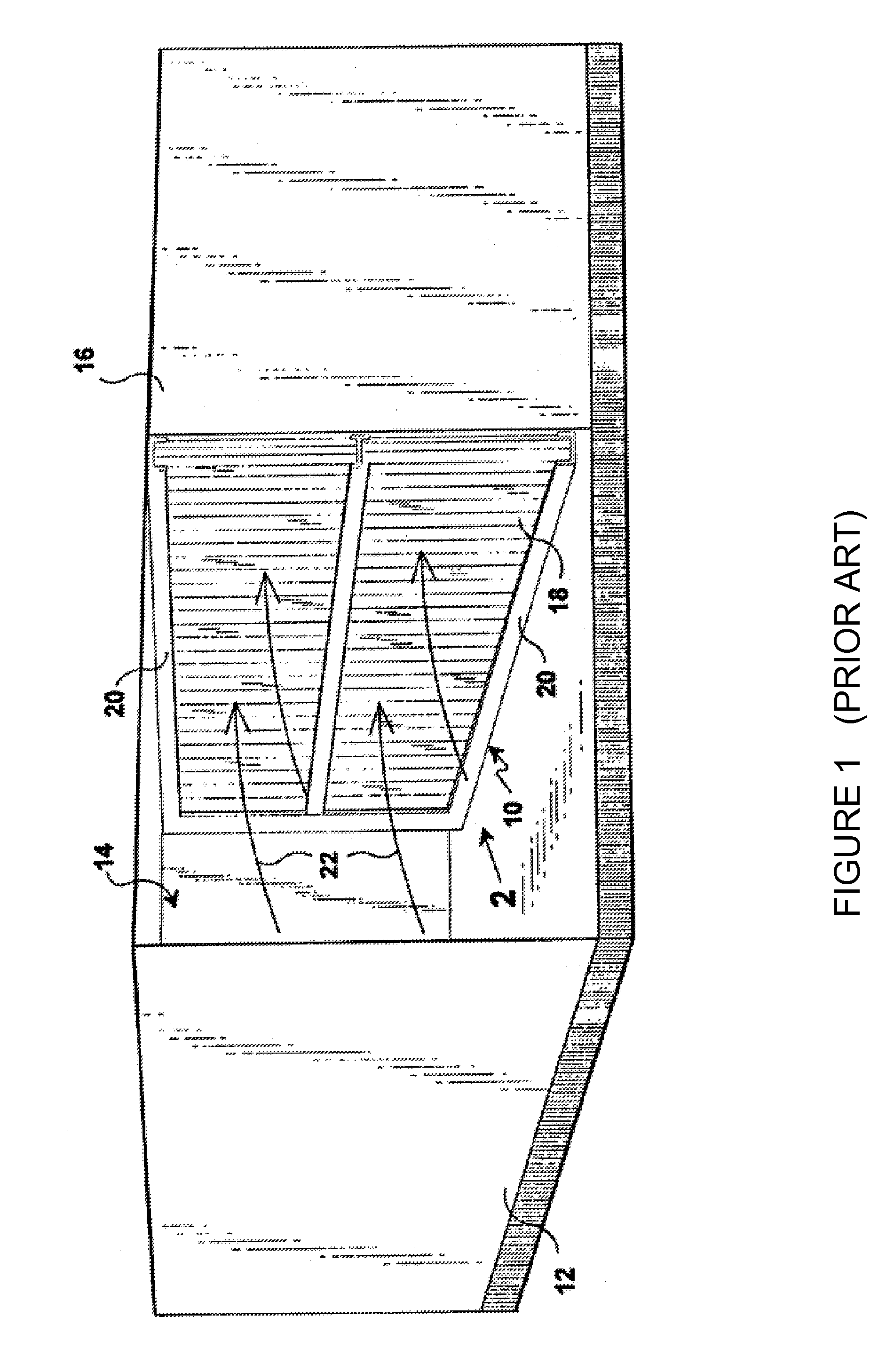
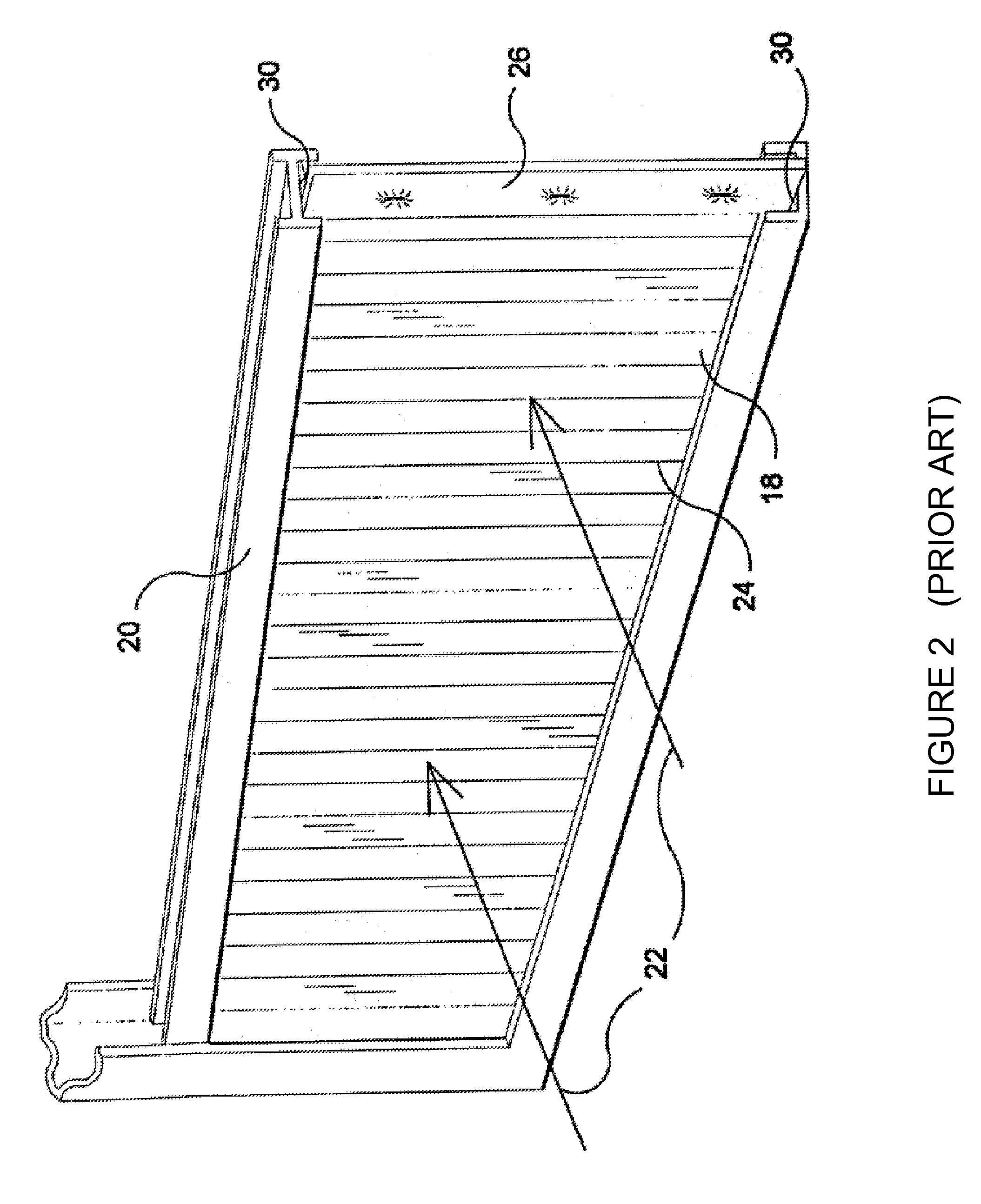
[0029]FIG. 1 illustrates a perspective view of a commercial air conditioning unit 12 having an access panel 14 removed from its housing 16 showing the prior Culwell device 10 comprising an onsite fabricated filter element 18 installed into the original equipment manufacturer's filter housing 20. The direction of air flow is indicated by arrows 22. The filter element 18 may comprise a mixture of natural and synthetic fibers. The air filter housing 20 forms a frame around the perimeter of the generally vertically standing filter 18 so that the filter 18 is contained and secured within the housing 20. The filter 18 has a pleated portion 24 and a non-pleated portion 26.

[0030]FIG. 2 shows ...


PUM

PropertyMeasurementUnit
diameteraaaaaaaaaa
diameteraaaaaaaaaa
diameteraaaaaaaaaa

Abstract

An air filter element partially-fabricated on site wherein one or more wire frames are fastened to one another to form a structure substantially conforming to the dimensions of the original equipment manufacturer's filter housing. One or more of the wire frames are flexibly attached to each other end-to-end by flexible attachment means, allowing the assembled filter unit to be inserted into the filter housing one frame at a time, with the frame sections yet to be inserted folded or directed off to one side, thus bypassing space restrictions. Flexible attachment means may comprise spring connectors. Also disclosed is an end-cap affixed to or formed at one or both ends of the filter element. The end-caps may also contain printed material, such as text or pictures, which may include instructions for use, identifying labels or symbols, or the like.

Description

[0001]This application claims priority to Provisional Patent Application No. 60 / 713,673, filed Sep. 2, 2005, by Matt Ashwood, and is entitled in whole or in part to that filing dates for priority. The specification, drawings, and attachments of Provisional Patent Application No. 60 / 713,673 are incorporated herein in their entirety by reference.FIELD OF INVENTION[0002]The present invention relates to heating, ventilating and air conditioning systems. More particularly, the present invention relates to a flexible or folding size adjustable filter element being partially fabricated on site wherein one or more wire frames are flexibly fastened to one another to form a structure substantially conforming to the unit's original equipment manufacturer's filter housing.BACKGROUND OF INVENTION[0003]There are numerous means for removing particle matter from atmospheric air before introducing said air into a heating, venting, and / or air conditioning system. Typically, these systems have one or ...

Claims


Application Information

Patent Timeline
Patent Type & Authority Patents(United States)
IPC IPC(8): B01D46/00B01D46/52
CPCB01D46/10B01D46/521F24F13/28B01D2265/06B01D2275/203Y10S55/31
Inventor ASHWOOD, MATTHEW P.KENT, DAVID M.
Owner BONDED FILTER
Why Eureka
Try Eureka