
Computer resource distribution method based on prediction

a computer resource and distribution method technology, applied in the field of computer resource distribution methods based on prediction, can solve the problems of a large number of idle computer resources present, and a large number of idle computer resources, so as to reduce the total number of computer resources, reduce the maintenance cost of surplus resources, and improve resource scheduling precision

Inactive Publication Date: 2009-03-03
HITACHI LTD
View PDF11 Cites 75 Cited by
  • Summary
  • Abstract
  • Description
  • Claims
  • Application Information

AI Technical Summary

Benefits of technology

The present invention provides a resource distribution method that allows multiple services or users to share computer resources, reducing the number of resources needed and lowering maintenance costs. The method improves resource scheduling, allowing efficient distribution. By automatically shifting standby system states, different services or users can share resources, and the precision of resource scheduling is improved. The invention also allows for prediction of service load increases and avoidance of resource lending to services with low reliability. Overall, the invention optimizes resource utilization and reduces costs.

Problems solved by technology

Here, the maintenance of idle computer resources and a resultant cost pose a problem.
Usually, therefore, a large number of idle computer resources are present.
Maintaining the computer resources constitutes a barrier to the cost reduction.
Therefore, the total number of servers cannot be decreased in the form of, for example, server integration.
In the case where the load varies depending upon the time zone, it is necessary to prepare enough computer resources to withstand a high load and it is difficult to reduce computer resources.
In addition, since the standby system becomes a computer resource group always having the same setting as that of the active system in the conventional technique, it is necessary to maintain a standby system every service and it is difficult to reduce the computer resources.
Furthermore, since overload in computer resources of the active system is predicted in the conventional technique on the basis of the current load value, precision of resource scheduling is low.
In that respect as well, it is difficult to form a configuration in which surplus resources are mutually lent among a plurality of services.

Method used


Image

  • Computer resource distribution method based on prediction
  • Computer resource distribution method based on prediction
  • Computer resource distribution method based on prediction

Examples


first embodiment

[0041]Hereafter, a first embodiment of the computer resource distribution method based on the prediction technique will be described in detail with reference to the drawings.

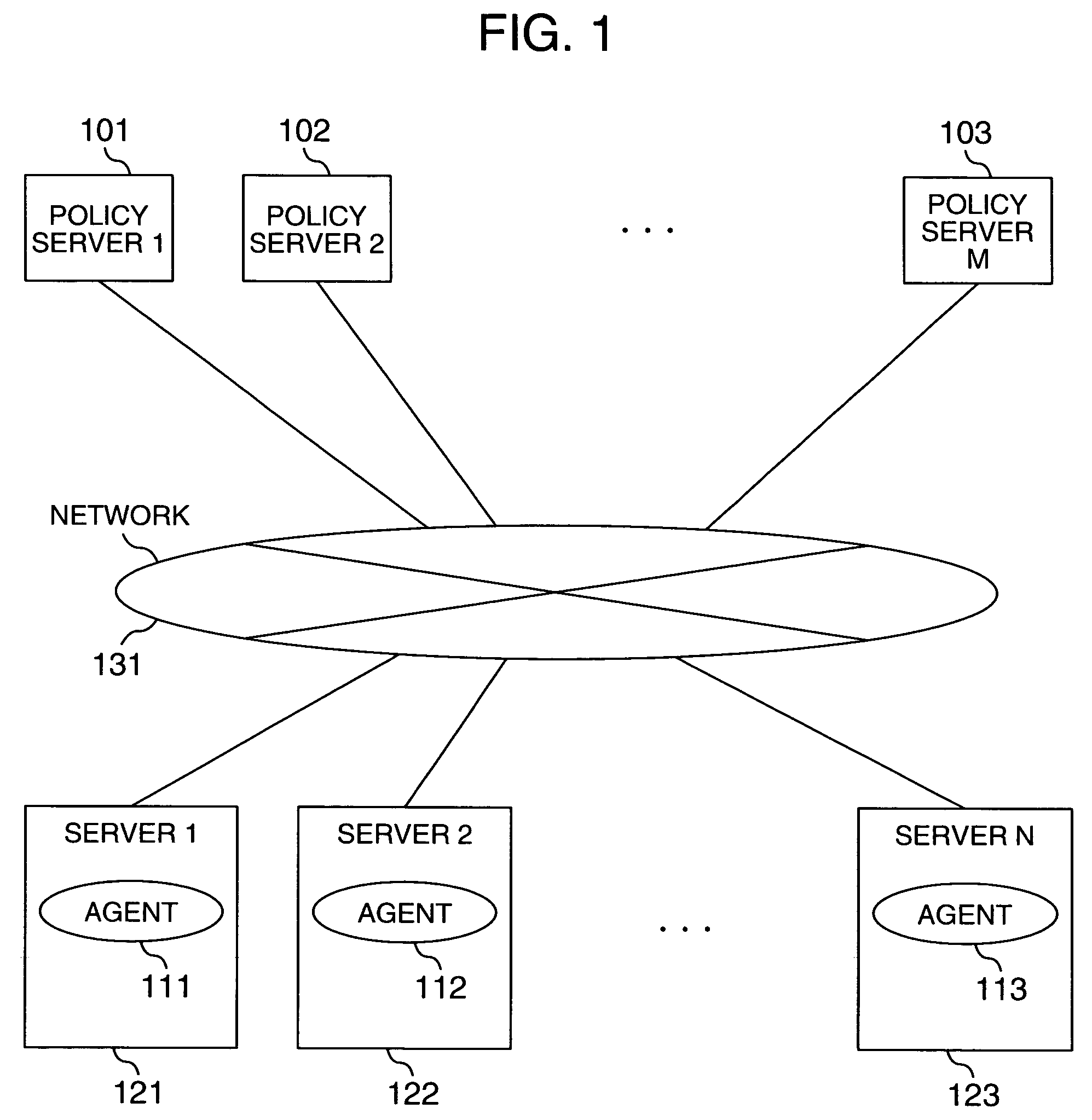
[0042]FIG. 1 shows how a plurality of policy servers 101, 102 and 103 are connected to a plurality of servers 121, 122 and 123 respectively having agents 111, 112 and 113 via a network 131 according to the computer resource distribution method based on prediction according to the present invention,

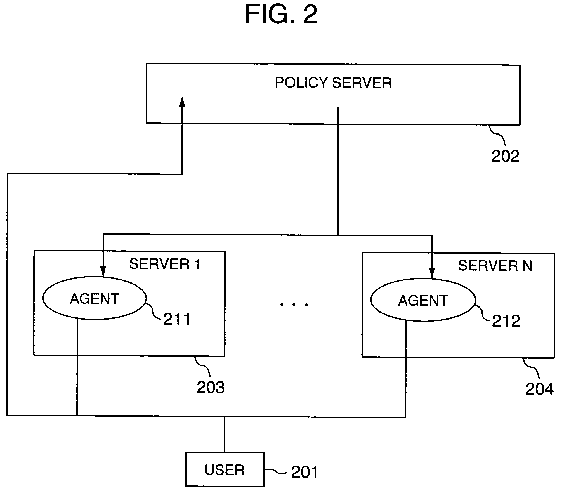
[0043]FIG. 2 is a schematic configuration diagram for the computer resource distribution method using a prediction technique according to the present invention. Reference numeral 201 denotes a user who utilizes a computer environment. A policy server 202 receives event information issued by the user 201 and agents 211 and 212 respectively in servers 203 and 204 (a schedule, load prediction, fault prediction and maintenance of the servers, and hardware information and software information issued by the agents 211 and 21...

second embodiment

[0057]Hereafter, a second embodiment of the computer resource distribution method based on the prediction technique will be described with reference to the drawings. In the second embodiment, a mechanism described in the first embodiment is used. In particular, a prediction portion concerning the load in the prediction mechanism shown in FIG. 6 will be described in detail.

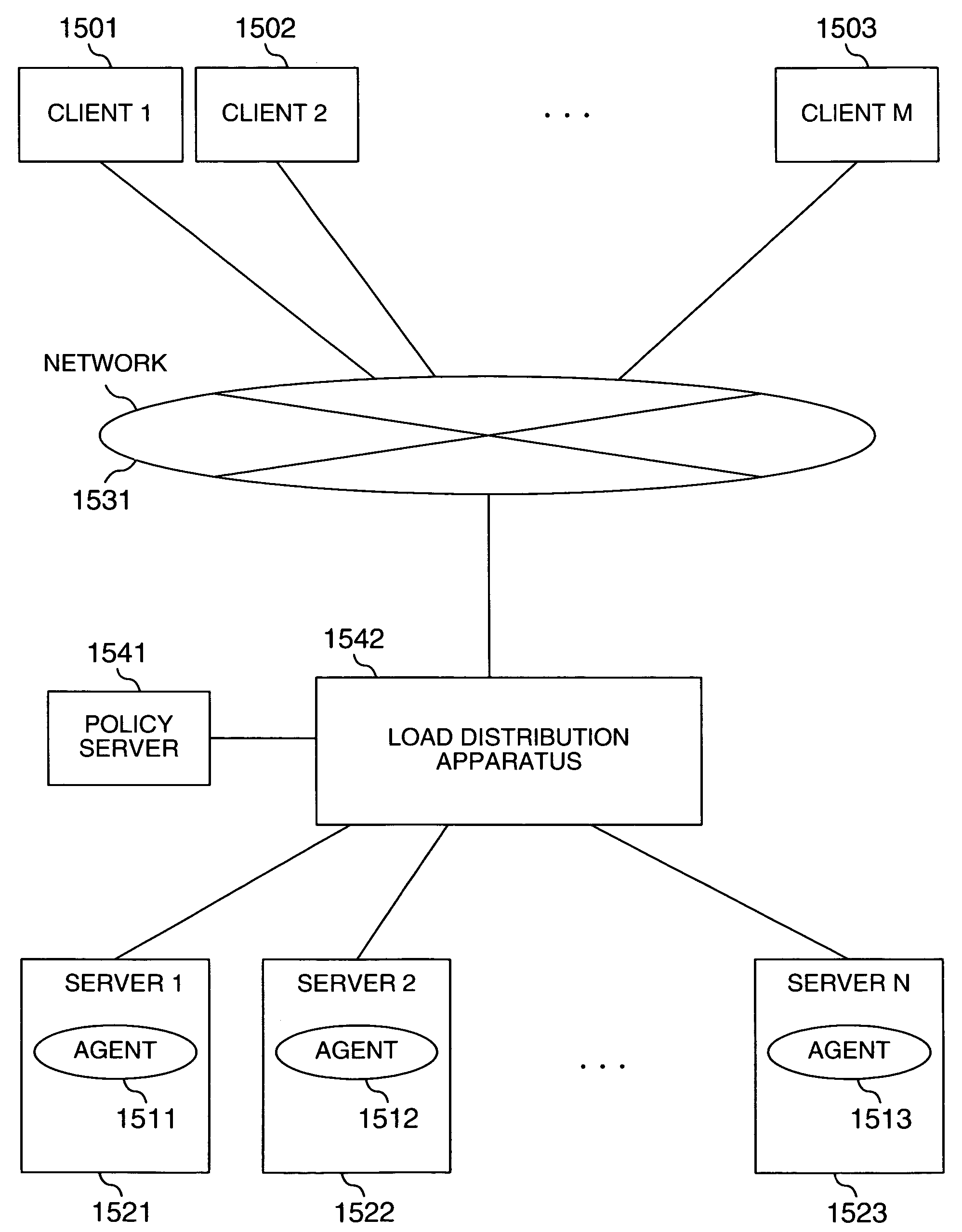
[0058]FIG. 15 shows how a plurality of clients 1501, 1502 and 1503 are connected to a plurality of servers 1521, 1522 and 1523 respectively having agents 1511, 1512 and 1513 via a load distribution apparatus 1542 and a network according to the computer resource distribution method based on prediction according to the present invention. A policy server 1541 is connected to the load distribution apparatus 1542.

[0059]FIG. 6 shows how servers 1621, 1622 and 1623 are clustered by at least one clustering software program 1643 instead of the load distribution apparatus 1542. As for the mechanism for thus distributing the ...


PUM


Abstract

A resource distribution method capable of lending surplus resources among a plurality of services and reducing the maintenance cost of the surplus resources is provided. Computer resources in the standby system have a dead standby state in which at least an application is not installed. A plurality of services or a plurality of users share the computer resources in the standby system. As a result, improvement of the utilization factor of idle computer resources and server integration are implemented, and the cost required to maintain the computer resources is reduced. Furthermore, load prediction is conducted as regards individual services by using past operation history. Idle computer resources secured from services having surplus and maintained are thrown in according to a result of the prediction.

Description

INCORPORATION BY REFERENCE[0001]The present application claims priority from Japanese application JP 2003-379291 filed on Nov. 10, 2003, the content of which is hereby incorporated by reference into this application.BACKGROUND OF THE INVENTION[0002]The present invention provides a method for automatically shifting computer resources from a standby system to an active system by using a prediction technique.[0003]In recent years, outsourcing with the object of reducing the necessary expense is proceeding in purchase, supply and maintenance of service, software and infrastructures. Computer use of “on demand” type has been proposed. In the computer use of “on demand” type, necessary computer resources are used when needed, and a charge is paid according to the amount used. Outsourcing to computer centers having a large quantity of computer resources represented by conventional computer centers such as data centers and utility centers is proceeding. It is considered that this movement w...

Claims


Application Information

Patent Timeline
Patent Type & Authority Patents(United States)
IPC IPC(8): G06F15/173G06F15/177G06F9/46G06F9/50
CPCG06F9/5011G06F9/5083G06F2209/5019
Inventor TAMESHIGE, TAKASHITAKAMOTO, YOSHIFUMI
Owner HITACHI LTD
Learn More