Apparatus to assist a patient's breathing with a variable ramp period to rise to treatment pressure

a technology of patient respiration and apparatus, which is applied in the direction of instruments, diagnostic recording/measuring, electronic commutators, etc., can solve the problems of not being able to fall asleep, not being able to really help patients, and being unable to help patients

Active Publication Date: 2009-03-10
KONINKLJIJKE PHILIPS NV
View PDF14 Cites 51 Cited by
  • Summary
  • Abstract
  • Description
  • Claims
  • Application Information

AI Technical Summary

Benefits of technology

[0012]a ramp module connected to the control unit in order to provide the control unit with the value of pressure PM to settle at the mask, so that when the apparatus starts functioning, the pressure progressively rises until the pressure of treatment PT;the apparatus comprising a comparator connected to the ramp module, means for detecting the patient's breathing parameters and sending them to said comparator, in order that in response to breathing parameters, the comparator is able to determine that an event occurs in patient's breathing and to send the corresponding data to the ramp module which provides the control unit with a value of pressure PM that will speed up with respect of the time, so that the rise of pressure at patient's mask is accelerated.
[0014]Such an apparatus has the advantage to generate a ramp period which can be modulated in the same ramp, according to patient's breathing parameters.

Problems solved by technology

However, such devices require from the patient a minimum of consciousness to activate the ramp cycles.
This is not really very efficient to fall asleep and it is not possible when the patient has fallen asleep.
Moreover each ramp can not be modified during the time when the ramp is activated.

Method used


Image

  • Apparatus to assist a patient's breathing with a variable ramp period to rise to treatment pressure
  • Apparatus to assist a patient's breathing with a variable ramp period to rise to treatment pressure
  • Apparatus to assist a patient's breathing with a variable ramp period to rise to treatment pressure

Examples


example 1

Variations of Value PM According to Different Events

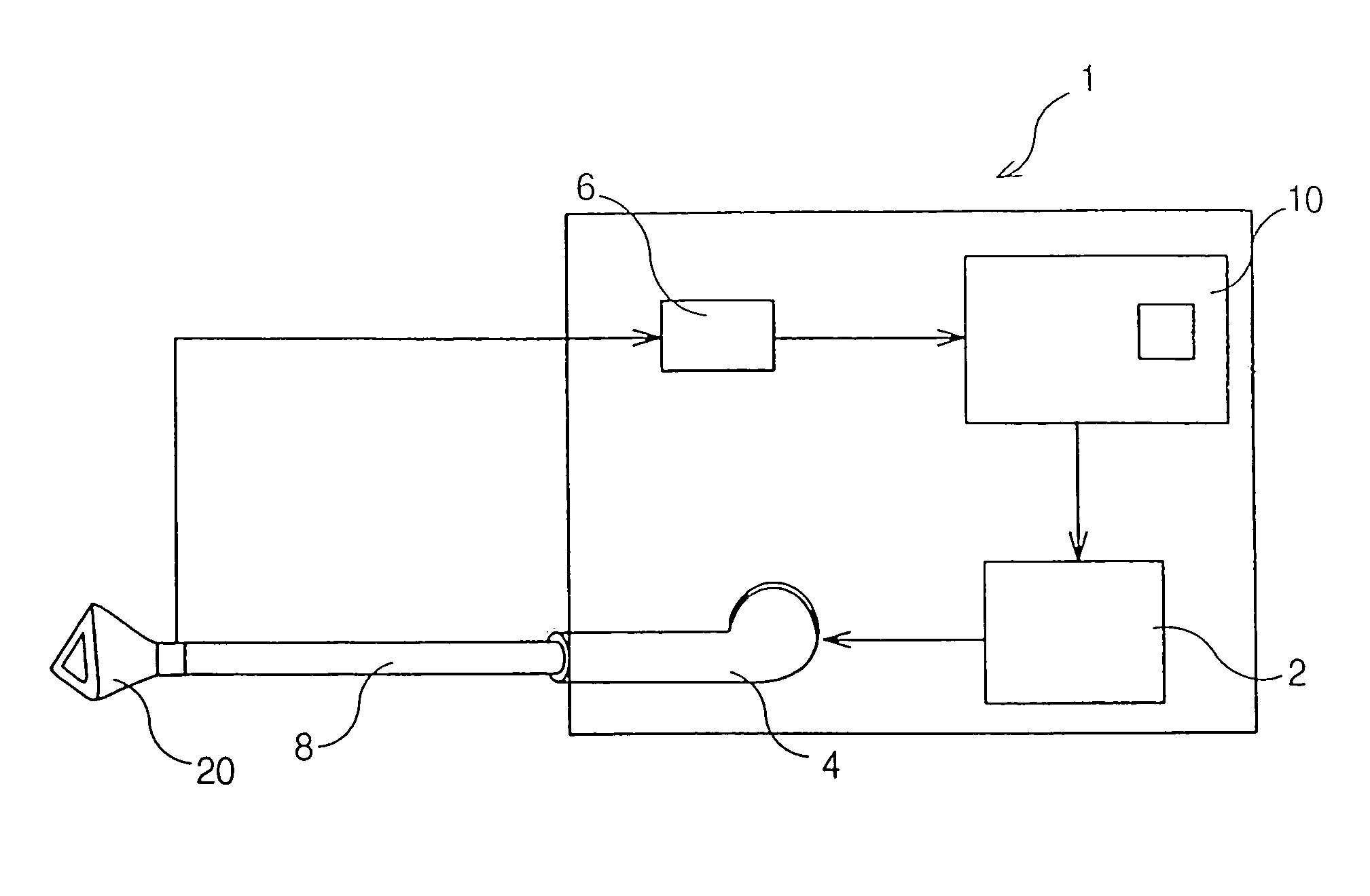
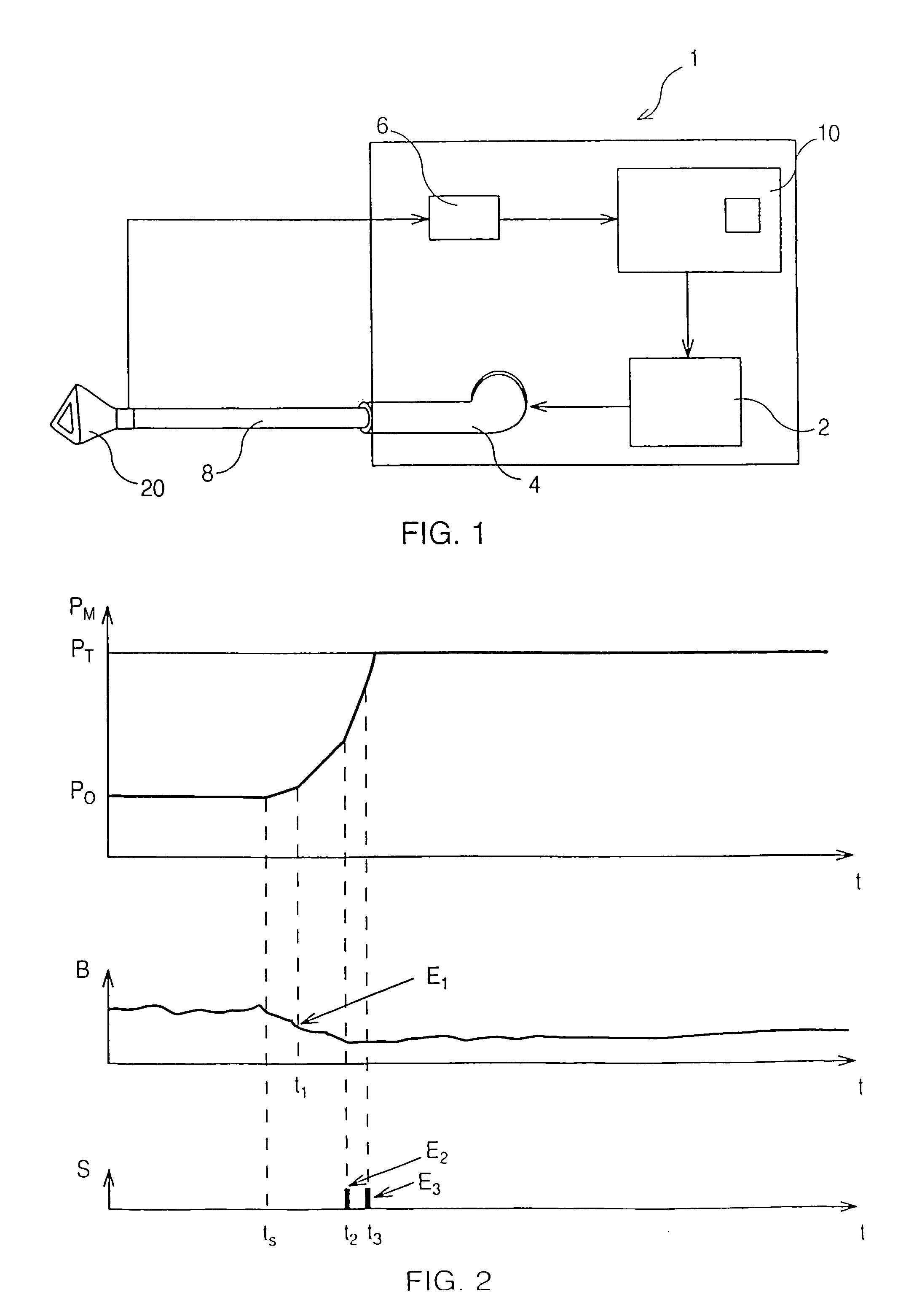
[0028]FIG. 2 represents one example of the apparatus functioning wherein three systems of coordinates are represented: pressure value PM as a function of time, patient's breathing B as a function of time and snoring S as a function of time. At a time tS, the ramp module 10 activates the rise in pressure. At time t1 as a slowdown E1 in breathing is detected, the rise in pressure is accelerated by the ramp module 10. Then at time t2 snoring E2 is detected. Thus, the rise in pressure is accelerated again by the ramp module. As at time t3 a snoring E3 is still detected the ramp module still accelerates the rise in pressure. As represented on FIG. 2, the preferred embodiment is a linear rise in pressure. Thus at time tS, the coefficient KRP of rise in pressure is constant. Each time an event is detected the module ramp adds a given constant value KE to this coefficient, the slope of the linear function being thus accentuated at each eve...

example 2

Example of Calculating the Value PM

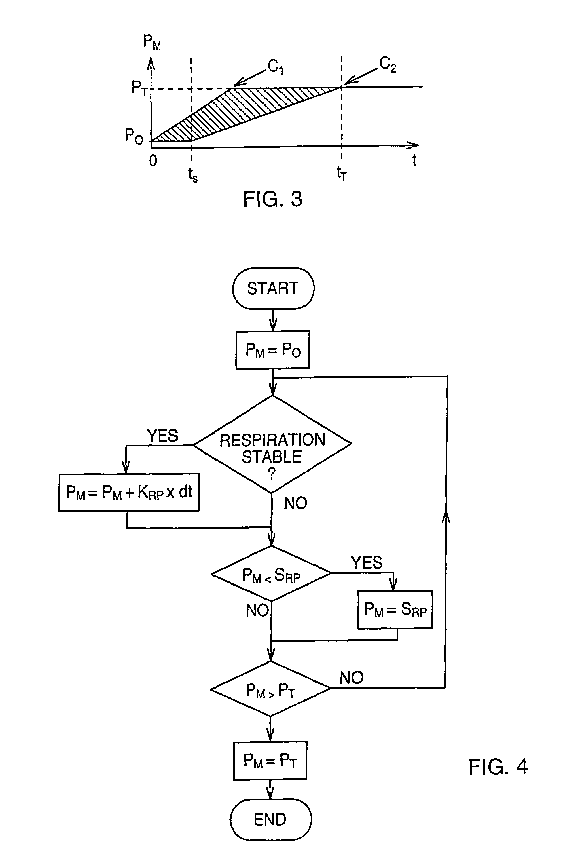
[0029]In this example the treatment pressure PT is of 10 hecto pascal (hPa). The initial pressure P0 of the air provided at patient's mask is 4 hPa. A physician has set that the ramp will start at a time ts of 2 minutes and has set the initial coefficient KRP at 0.2 hPa per minute (hPa / mn). The physician also set that when a snoring is detected KE equals 1 hPa when the breath rate is below a set threshold.

[0030]When the apparatus starts the control units supply the blower in order to set at the patient's mask a pressure of 4 hPa. After 2 minutes, the ramp module starts increasing the value PM. As no events occurs, the coefficient KRP stays at 0.2 hPa. After 10 minutes the value PM is of 5.6 hPa (8 minutes multiplied by 0.2 hPa / mn and added to the 4 hPa). After these ten minutes, the patient's breath is below threshold. The ramp module adds the corresponding KE value to the coefficient KRP, which thus equals 1.2 hPa / mn. The treatment pressure is th...


PUM


Abstract

An apparatus (1) to assist a patient's respiration by delivering air to a patient through a mask (20), including a ramp module (10) connected to a control unit (2) to provide the control unit with a pressure value PM at mask (20), so that when apparatus (1) starts functioning, the pressure progressively rises until it reaches a treatment pressure PTi, the apparatus further including a comparator connected to ramp module (10), at least one device for detecting the patient's breathing parameters and sending them to the comparator, so that the comparator can determine whether an event (E1, E2 or E3) occurs in patient's breathing and to send the corresponding data to ramp module (10) which provides control unit (2) with a pressure value PM that will speed up with respect of time, so that the pressure rise at patient's mask (20) is accelerated.

Description

[0001]This application is a U.S. National Stage of International Application PCT / IB03 / 01422, filed Mar. 10, 2003, and claims priority of U.S. provisional application Ser. No. 60 / 362,441, filed Mar. 8, 2002.TECHNICAL FIELD[0002]This invention concerns the field of apparatus to assist a patient respiration and more specifically an apparatus bringing progressively to the pressure of treatment the air the patient is provided with.BACKGROUND ART[0003]In many treatments apparatus are used to provide patients with air. More frequently they are used for patients with a breathing deficiency caused for example by the weakness of the breathing system or by obstructive apneas during the sleep. In those cases it is important to control the pressure of the air delivered to the patient. With respiratory insufficient patients, apparatus providing air at a higher pressure help to compensate the weakness of the patients lungs. In the case of patients suffering of sleep apneas, providing the air at a ...

Claims


Application Information

Patent Timeline
Patent Type & Authority Patents(United States)
IPC IPC(8): A61M16/00A62B7/00F16K31/02A61B5/087H02P6/00H02P6/18
CPCA61M16/00A61M16/0057H02P6/001H02P6/182A61M16/0069A61B5/087A61M2016/0021A61M2016/0039A61M2016/0042A61M2205/70A61M2230/42H02P6/34A61M16/024
Inventor DELACHE, ALAINDELACHE, VERONIQUE
Owner KONINKLJIJKE PHILIPS NV
Why Eureka
Try Eureka