Method for adjusting electro-optical apparatus, adjusting apparatus of electro-optical apparatus, and electronic system

a technology of electrooptical apparatus and adjusting apparatus, which is applied in the field of electrooptical apparatus adjusting apparatus, electronic system, etc., can solve problems such as deterioration of liquid crystal characteristics, and achieve the effect of suppressing flicker and reducing the variation amount of light emitted

Inactive Publication Date: 2009-03-10
SEIKO EPSON CORP
View PDF14 Cites 2 Cited by
  • Summary
  • Abstract
  • Description
  • Claims
  • Application Information

AI Technical Summary

Benefits of technology

[0011]In an electro-optical apparatus having the above-described structure, the voltage held between the pixel electrode and the opposing electrode in a horizontal scanning period gradually decreases when the switching element is in an off state (specifically, when the scanning line is not selected). This is because a current leaks from the pixel electrode through the switching element. Meanwhile, at this time, the leakage amount (degree of leakage) of when the image signal is positive may differ from that of when the image signal is negative. Specifically, the leakage amount of when the positive image signal is supplied is larger than that of when the negative image signal is supplied. Accordingly, the variation amount (attenuation amount) per unit time of the voltage held by the pixel electrode when the image signal is positive becomes larger than that of when the image signal is negative. In this manner, since there is a difference in the attenuation characteristics, given that the effective voltage value to the liquid crystal when the image signal is positive polarity is almost the same as that of when image signal is negative polarity, the amount of light emitted from the liquid crystal device viewed by an observer is different in both cases. Thus, if the common potential is selected so as to minimize a flicker, the result is that the effective voltage value to the liquid crystal when the image signal is positive polarity differs from that of when the image signal is negative polarity. Specifically, the common potential selected in order to minimize a flicker becomes smaller than the potential to eliminate the difference in the effective voltage value to the liquid crystal. Thus, in an exemplary aspect of the present invention, a potential higher than the potential which minimizes a flicker is selected as the common potential. By this method, it is possible to make the effective voltage value of when the image signal is positive polarity come close or be equal to the effective voltage value of when the image signal is negative polarity. Thus, the deterioration of the electro-optical material due to application of a direct current component can be suppressed. Furthermore, the common potential selected in this manner is close to the potential to minimize a flicker, and thus the generation of the flicker is suppressed.
[0012]In an electro-optical apparatus, the polarity of the image signal is inverted for each specific period, such as a horizontal scanning period and a vertical scanning period. In the structure in which the polarity of the image signal is inverted for each one or a plurality of vertical scanning periods, it is desirable to supply the image signal corresponding to an intermediate grayscale to each of the plurality of pixel electrodes. In general, in the case of an intermediate grayscale, it is easier to obtain the variation of light emitted from an electro-optical apparatus compared with the cases of the lowest grayscale (black) and the highest grayscale (white). Thus, with this arrangement, even if the variation amount of light emitted from the electro-optical apparatus is very little, it is possible to obtain this variation amount.
[0013]Also, an electro-optical apparatus may adopt a structure (structure which adopts so-called line inversion, column inversion, and pixel inversion) in which a plurality of pixel electrodes are divided into a first group and a second group, and the polarity of the image signal supplied to each pixel electrode is inverted such that the polarity of the image signal supplied to the pixel electrodes included in the first group is the opposite to the polarity of the image signal supplied to the pixel electrodes included in the second group. With this arrangement, if an intermediate grayscale is displayed by all the pixel electrodes, for each vertical scanning period, pixels emitting light by a positive image signal and pixels emitting light by a negative image signal are mixed. Thus it becomes difficult to recognize the variation of light emitted in accordance with the polarity of the image signal. Accordingly, when adjusting an electro-optical apparatus having this structure, it is desirable to supply the image signal corresponding to an intermediate grayscale to the pixel electrodes included in the first group, and to supply the image signal corresponding to the lowest grayscale to the pixel electrodes included in the second group. In this mode, out of the first group and the second group whose image signals have polarities opposite to each other, the amount of light emitted from the pixel electrodes included in the second group is suppressed. Thus it is possible to selectively confirm only the amount of emitted light of an intermediate grayscale displayed by the pixel electrodes included in the first group. Accordingly, it becomes possible to easily recognize the variation of the amount of emitted light in accordance with the polarity of the image signal.
[0016]In this regard, an exemplary aspect of the present invention can be identified as an apparatus to adjust the common potential in an electro-optical apparatus. Specifically, according to an exemplary aspect of the present invention, there is provided an adjusting apparatus including a light receiving device which receives light emitted from the electro-optical apparatus and outputs an electrical signal in accordance with the received light amount; an adjusting device which adjusts a common potential to a potential causing the electronic signal output from the light receiving device to have a minimum amplitude (specifically, in order to minimize the variation amount of light emitted from the electro-optical apparatus); and a setting device which sets the common potential to a potential higher than the potential adjusted by the adjusting device. By this adjusting apparatus, for the same reason as the adjusting method described above, it is possible to reduce a direct current component applied to the electro-optical material, and to suppress a flicker. In this regard, a structure, which is further provided with a display control device to indicate an image to be displayed to the electro-optical apparatus in the first step, may be adopted. The image content (a grayscale indicated by the image signal) indicated in the electro-optical apparatus with this structure is the same as the example shown for the adjusting method described above.

Problems solved by technology

When the effective voltage value differs in this manner, a direct current component of a voltage is kept applied to the liquid crystal, thereby causing the deterioration of the characteristics of the liquid crystal.

Method used


Image

  • Method for adjusting electro-optical apparatus, adjusting apparatus of electro-optical apparatus, and electronic system
  • Method for adjusting electro-optical apparatus, adjusting apparatus of electro-optical apparatus, and electronic system
  • Method for adjusting electro-optical apparatus, adjusting apparatus of electro-optical apparatus, and electronic system

Examples


Embodiment Construction

A: Configuration of Liquid Crystal Device

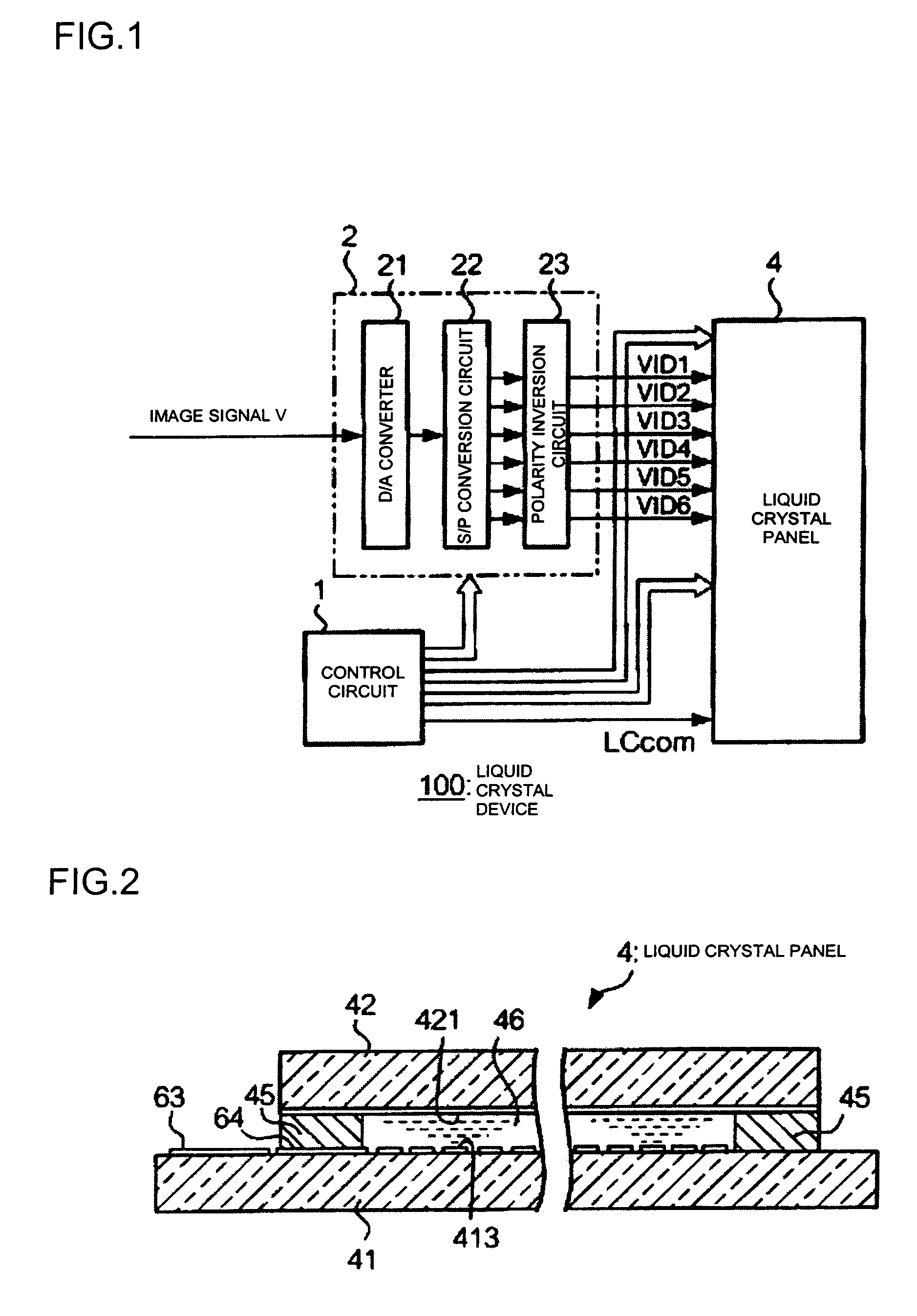
[0027]First, a description will be given of an exemplary embodiment of an electro-optical apparatus whose common potential is adjusted by the method according to an exemplary aspect of the present invention. This electro-optical apparatus is a liquid crystal device which adopts a liquid crystal as an electro-optical material. As shown in FIG. 1, a liquid crystal device 100 has a control circuit 1, an image signal processing circuit 2, and a liquid crystal panel 4. Among these, the control circuit 1 is a circuit to control each part of the liquid crystal device 100 based on the control signals supplied from various upper units, such as a CPU (Central Processing Unit) of an electronic system in which the liquid crystal device 100 is mounted.

[0028]The image signal processing circuit 2 is a circuit to process a digital image signal V supplied from an upper unit to output a signal suited to be supplied to the liquid crystal panel 4. The image sign...


PUM

PropertyMeasurementUnit
frequencyaaaaaaaaaa
frequencyaaaaaaaaaa
electro-opticalaaaaaaaaaa

Abstract

A liquid crystal device has a pixel electrode connected to a scanning line and a data line through a TFT, and an opposing electrode opposed to the pixel electrode with a liquid crystal sandwiched therebetween. An almost constant common potential LCcom is applied to the opposing electrode. When this common potential LCcom is adjusted, first, the common potential LCcom is adjusted to a potential Vcom′, which minimizes the variation amount of light emitted from the liquid crystal device in the course of displaying a specific image, and, second, the common potential LCcom is set to a potential V0, which is higher than the potential Vcom′. Thus, it is possible to select, in an easy procedure, a common potential which can suppress a flicker while reducing a direct current component applied to the electro-optical material.

Description

BACKGROUND OF THE INVENTION[0001]1. Field of Invention[0002]Exemplary aspects of the present invention relate to a technique for adjusting a potential (referred to as “common potential”) to be applied to an opposing electrode of an electro-optical apparatus.[0003]2. Description of Related Art[0004]In a related art electro-optical apparatus which displays an image using an electro-optical material, such as a liquid crystal, in particular, alternating current drive is adopted in order to prevent the deterioration of the characteristics of the electro-optical material. For example, in an active matrix liquid crystal device using a thin film transistor as a switching element, an almost constant common potential is applied to an opposing electrode opposed to a plurality of pixel electrodes with a liquid crystal sandwiched. At the same time, an image signal indicating the content of an image is periodically inverted using a predetermined potential as a reference, and then is supplied to e...

Claims


Application Information

Patent Timeline
Patent Type & Authority Patents(United States)
IPC IPC(8): G09G3/36G06F3/038G09G5/00G09G5/02G09G5/10G01R31/00G02F1/133G09G3/20
CPCG09G3/3614G09G3/3655G09G3/3688G09G2310/0218G09G2320/0247G09G3/36
Inventor AOKI, TORU
Owner SEIKO EPSON CORP
Why Eureka
Try Eureka