Compensating for thermal expansion when writing spiral tracks to a disk of a disk drive

a disk drive and spiral track technology, applied in the field of disk drives, can solve the problems of thermal expansion not being uniform around the circumference of the disk, external servo writers are expensive and require a clean room environment, and external servo writers have become an expensive bottleneck in the disk drive manufacturing process,

Inactive Publication Date: 2009-03-10
WESTERN DIGITAL TECH INC
View PDF22 Cites 117 Cited by
  • Summary
  • Abstract
  • Description
  • Claims
  • Application Information

AI Technical Summary

Benefits of technology

[0013]In another embodiment, the distance delta D_Δ generated for a first spiral track is saved, and a difference is generated between the distance delta D_Δ generated for a second spiral track and the distance delta D_Δ generated for the first spiral track. If the difference exceeds a threshold, the at least one of the starting radial location and the velocity profile is adjusted in response to the distance delta D_Δ generated for the first spiral track. The second spiral track is written to the disk using the starting radial location and the velocity profile.

Problems solved by technology

However, external servo writers are expensive and require a clean room environment so that a head positioning pin can be inserted into the head disk assembly (HDA) without contaminating the disk.
Thus, external servo writers have become an expensive bottleneck in the disk drive manufacturing process.
In addition, the effect of thermal expansion may not be uniform around the circumference of the disk (relative to the head).
If the spiral tracks are written without compensating for this thermal expansion, the resulting non-uniform spacing between the spiral tracks may degrade and / or render the product servo sectors inoperable.

Method used


Image

  • Compensating for thermal expansion when writing spiral tracks to a disk of a disk drive
  • Compensating for thermal expansion when writing spiral tracks to a disk of a disk drive
  • Compensating for thermal expansion when writing spiral tracks to a disk of a disk drive

Examples


Embodiment Construction

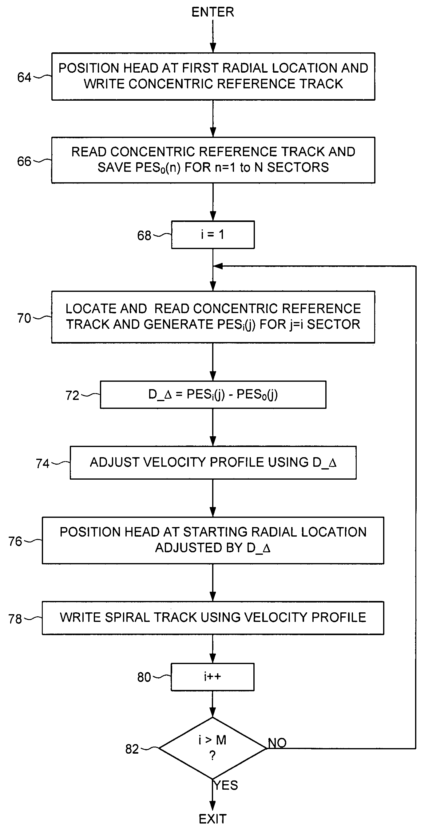
[0025]An embodiment of the present invention comprises a method of writing M spiral tracks (i=1 to M) to a disk of a disk drive. A head is positioned over a first radial location and a first concentric reference track is written, the first concentric reference track comprising N concentric servo sectors. Prior to writing one of the spiral tracks, the head is positioned over the first concentric reference track to read the first concentric reference track, and a position error signal first_PESi(j) is generated for at least one of the servo sectors j in the first concentric reference track, wherein the first_PESi(j) represents an offset of the head from the first radial location, and the servo sector j corresponds to a circumferential location of the spiral track. At least one of a starting radial location and a velocity profile is adjusted in response to the first_PESi(j), and the spiral track is written to the disk using the starting radial location and the velocity profile.

[0026]Th...


PUM

PropertyMeasurementUnit
distanceaaaaaaaaaa
velocityaaaaaaaaaa
thermal expansionaaaaaaaaaa

Abstract

A method is disclosed for writing M spiral tracks (i=1 to M) to a disk of a disk drive. A head is positioned over a first radial location to write a concentric reference track comprising N concentric servo sectors. Prior to writing one of the spiral tracks, the concentric reference track is read and a position error signal first_PESi(j) is generated for at least one of the servo sectors j in the concentric reference track, wherein the first_PESi(j) represents an offset of the head from the first radial location, and the servo sector j corresponds to a circumferential location of the spiral track. At least one of a starting radial location and a velocity profile is adjusted in response to the first_PESi(j), and the spiral track is written to the disk using the starting radial location and the velocity profile.

Description

BACKGROUND[0001]1. Field[0002]The present invention relates to disk drives for computer systems. More particularly, the present invention compensates for thermal expansion when writing spiral tracks to a disk of a disk drive.[0003]2. Description of the Related Art[0004]When manufacturing a disk drive, product servo sectors 20-2N are written to a disk 4 which define a plurality of radially-spaced, concentric servo tracks 6 as shown in the prior art disk format of FIG. 1. The product servo sectors are said to form servo wedges or servo spokes from the outer to inner diameter of the disk. Each product servo sector (e.g., servo sector 24) comprises a preamble 8 for synchronizing gain control and timing recovery, a sync mark 10 for synchronizing to a data field 12 comprising coarse head positioning information such as a track number, and servo bursts 14 which provide fine head positioning information. During normal operation, the servo bursts 14 are processed by the disk drive in order t...

Claims


Application Information

Patent Timeline
Patent Type & Authority Patents(United States)
IPC IPC(8): G11B21/02
CPCG11B5/59627G11B5/59644G11B5/59661G11B5/59666
Inventor WU, HSUEH-CHIEHKON, KENNETH R.
Owner WESTERN DIGITAL TECH INC
Why Eureka
Try Eureka