Method and system for controlling a notching mechanism

a notching mechanism and control method technology, applied in the field of wireless networks, can solve the problems of more narrowband interfering signals, interference signals, and inability to predict at what frequencies an interference signal occurs

Inactive Publication Date: 2009-03-10
NORTH STAR INNOVATIONS
View PDF14 Cites 5 Cited by
  • Summary
  • Abstract
  • Description
  • Claims
  • Application Information

AI Technical Summary

Benefits of technology

[0019]The instant disclosure is provided to further explain in an enabling fashion the best modes of performing one or more embodiments of the present invention. The disclosure is further offered to enhance an understanding and appreciation for the inventive principles and advantages thereof, rather than to limit in any manner the invention. The invention is defined solely by the appended claims including any amendments made during the pendency of this application and all equivalents of those claims as issued.

Problems solved by technology

One problem that can arise in any network, but which is particularly troublesome in wider bandwidth systems is that of interfering signals.
When a network broadcasts over a large spectrum there may be one or more narrowband interfering signals within that broadcast spectrum.
However, for intermittent or local interfering signals, there may be no way to predict at what frequencies an interfering signal might be at.

Method used


Image

  • Method and system for controlling a notching mechanism
  • Method and system for controlling a notching mechanism
  • Method and system for controlling a notching mechanism

Examples


first embodiment

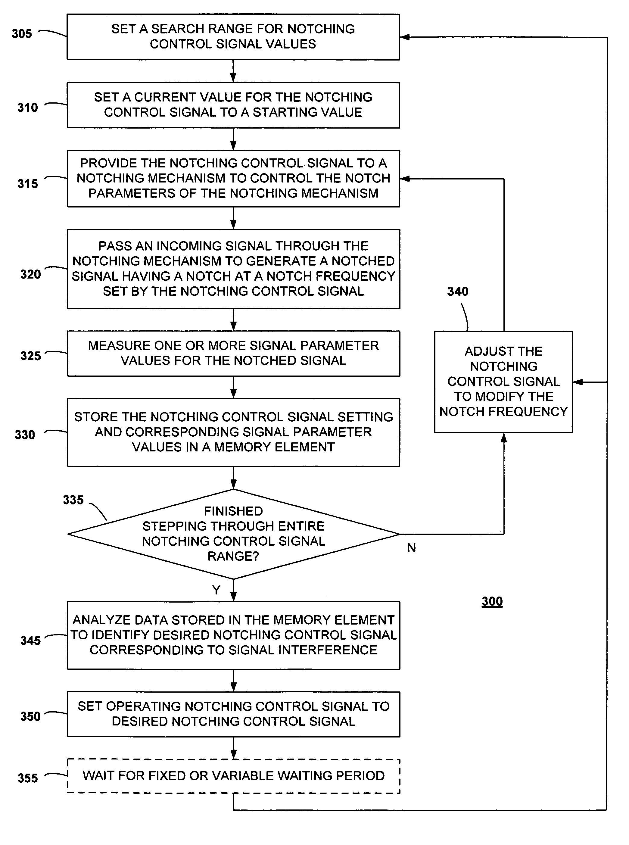
[0023]FIG. 1 is a block diagram of a transceiver including a notching control circuit, according to a first disclosed embodiment of the present invention. As shown in FIG. 1, a transceiver 100 includes an antenna 105, a notching mechanism 110, a low noise amplifier (LNA) 120, a correlator circuit 125, a RAKE circuit 130, an equalizer circuit 135, additional receiver circuitry 140, a transmitter amplifier 145, transmitter circuitry 150, a controller 155, a memory element 160, and one or more of a first signal parameter detector 165, a second signal parameter detector 170, a third signal parameter detector 175, a fourth signal parameter detector 180, and a fifth signal parameter detector 185.

[0024]The antenna 105 is configured to transmit and receive signals over a bandwidth used by the transceiver 100. It can be any sort of antenna that is suitable to the type of transceiver 100 used.

[0025]The notching mechanism 110 is a notching device whose notching frequency (and possibly other no...

second embodiment

[0060]FIG. 4 is a block diagram of a receiver including a notching control circuit, according to a second disclosed embodiment of the present invention. In this embodiment, multiple notching mechanisms are employed.

[0061]As shown in FIG. 4, a transceiver 400 includes an antenna 105, a low noise amplifier (LNA) 120, receiver circuitry 440, a transmitter amplifier 145, transmitter circuitry 150, a controller 455, a memory element 460, a signal parameter detector 485, and two or more of a first notching mechanism 410, a second notching mechanism 412, a third notching mechanism 414, and a fourth notching mechanism 416.

[0062]The antenna 105, LNA 120, transmitter amplifier 145, and transmitter circuitry 150 operate as described above with respect to FIG. 1. The receiver circuitry 440 includes all of the signal processing on the receiver path downstream of the LNA 120. This could include correlators, RAKE, equalizers, etc.

[0063]The first notching mechanism 410 is placed between the antenna...

third embodiment

[0070]FIG. 5 is a block diagram of a receiver including a notching control circuit, according to a third disclosed embodiment of the present invention. In this embodiment, two notching mechanisms are used at different parts of a circuit such that there is not a direct correspondence of their notching controls signals and their notching frequencies.

[0071]As shown in FIG. 5, a receiver 500 includes an antenna 105, a first notching mechanism 510, a low noise amplifier (LNA) 120, a receiver amplifier 538, receiver circuitry 540, a controller 555, a memory element 560, a signal parameter detector 485, a mixer 590, and a local oscillator 595, and may include a second notching mechanism 512.

[0072]The antenna 105 and the LNA 120 both operate as described above with respect to FIG. 1.

[0073]The first notching mechanism 510 is placed between the mixer 590 and the receiver amplifier 538 and notches signals in a baseband portion of the receiver path. The second notching mechanism 512, if it is i...


PUM


Abstract

A circuit (100) is provided for notching an incoming wireless signal. The circuit comprises: a notching mechanism (110) for receiving an incoming signal and generating a notched signal having reduced power at the notch frequency (320), the notch frequency being adjustable in response to a notching control signal; a signal parameter detector (165, 170, 175, 180, 185) for detecting a signal parameter of the notched signal (325); a controller (155) for receiving the signal parameter and for generating the notching control signal (315), the controller being configured to vary the signal parameter within a notching control signal range (340); and a memory (160) for storing the signal parameter and the notching control signal received from the controller in a notching database (330). The controller is configured to analyze the notching database to determine an optimal notching control signal to achieve a desired level of signal performance (345).

Description

RELATED INVENTIONS[0001]The present invention relates to U.S. patent application No. 11 / 237,751, entitled “FREQUENCY-NOTCHING ANTENNA,” by John W. McCorkle, filed Sep. 29, 2005, now issued as U.S. Pat. No. 7,352,333.FIELD OF THE INVENTION[0002]The present invention relates in general to wireless networks in which signal notching is used, and more specifically to a circuit and method for controlling the location of an adjustable notch in one or more notching mechanisms.BACKGROUND OF THE INVENTION[0003]Any wireless network will broadcast its signals over a set frequency spectrum. In the case of narrowband networks, this will be a relatively short frequency spectrum. But the spectrum used for signals will increase as networks move to wideband and ultrawide bandwidth (UWB) broadcasting systems.[0004]One problem that can arise in any network, but which is particularly troublesome in wider bandwidth systems is that of interfering signals. When a network broadcasts over a large spectrum th...

Claims


Application Information

Patent Timeline
Patent Type & Authority Patents(United States)
IPC IPC(8): H04B3/46H04B17/00H04Q1/20
CPCH04B1/1036
Inventor MCCORKLE, JOHN W.MILLER, TIMOTHY R.
Owner NORTH STAR INNOVATIONS
Why Eureka
Try Eureka