
Wireless system using continuous wave phase measurement for high-precision distance measurement

a phase measurement and wireless technology, applied in the direction of direction finders, instruments, measurement devices, etc., can solve the problems of surges, mudflows, landslides, etc., and achieve the accuracy required for natural hazard prediction, assessment and mitigation

Active Publication Date: 2009-03-17
SOUTHWEST RES INST
View PDF25 Cites 25 Cited by
  • Summary
  • Abstract
  • Description
  • Claims
  • Application Information

AI Technical Summary

Benefits of technology

The patent text describes a new method for measuring distance using continuous wave (CW) phase measurement, which is not limited by power and synchronization difficulties. This method uses an active reflector and does not require distributed oscillator synchronization, making it more accurate and reliable for applications such as natural hazard prediction, assessment, and mitigation. The technical effect of this invention is to provide a more accurate and reliable method for measuring distance in wireless sensor networks, which can be used for various practical applications.

Problems solved by technology

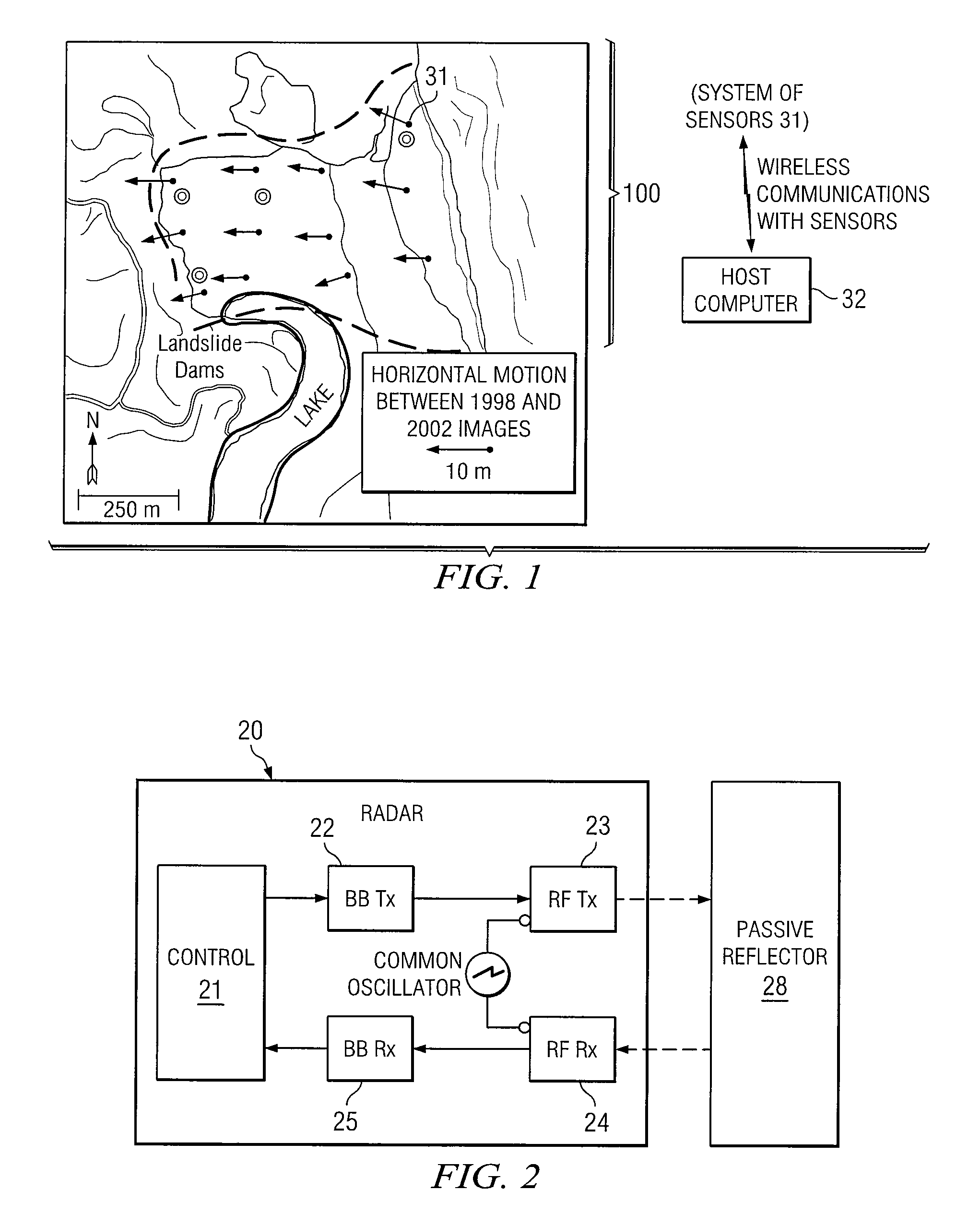
Many natural hazards (landslides, mud-flows, volcanic eruptions, floods, glacial surges) develop with time scales that are too short and conditions that are too dangerous for traditional field deployment.
Although various wireless sensor node distance measurement techniques have been proposed, none approach the accuracy required for natural hazard prediction, assessment and mitigation.

Method used


Image

  • Wireless system using continuous wave phase measurement for high-precision distance measurement
  • Wireless system using continuous wave phase measurement for high-precision distance measurement
  • Wireless system using continuous wave phase measurement for high-precision distance measurement

Examples


Embodiment Construction

[0014]As stated in the Background, EM-based distance measurement instruments have been previously implemented using phase difference measurements between separate frequency continuous EM wave returns. In EM-based distance measuring systems generally, distance is derived from the time it takes for a signal to be propagated along a propagation path corresponding in length to the distance to be measured. In continuous wave systems, as opposed to pulse systems, the signal is a sine wave signal of known frequency, and the travel time is measured by determining the phase delay experienced by the signal in being propagated along the propagation path.

[0015]Thus, by knowing the phase delay and the wavelength of the sine wave resulting from propagation of the signal, the distance can be determined. To determine the phase delay, the phase of the signal before propagation is compared with the phase of the signal after propagation. This results in a phase measurement which represents only the fr...


PUM


Abstract

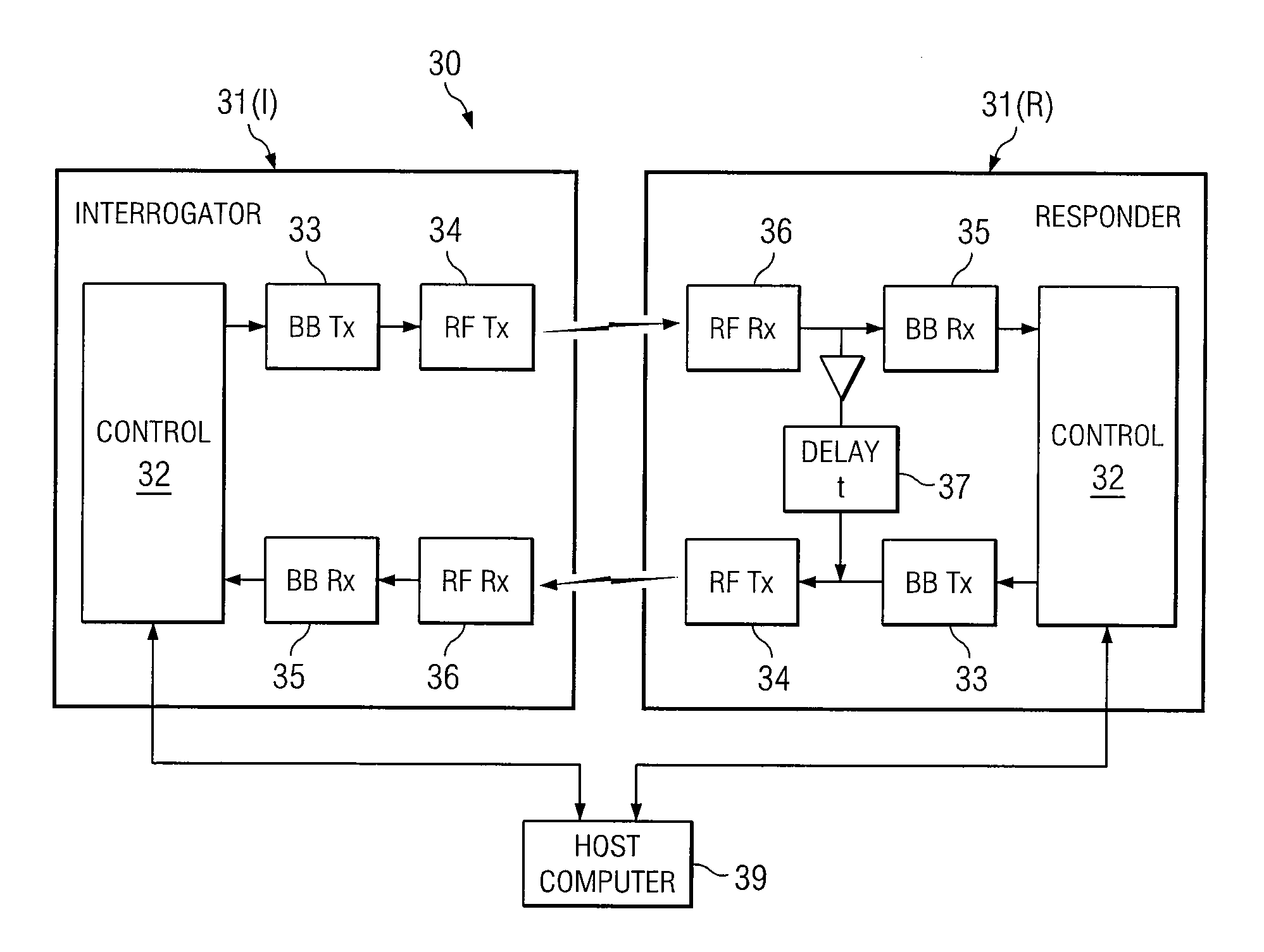
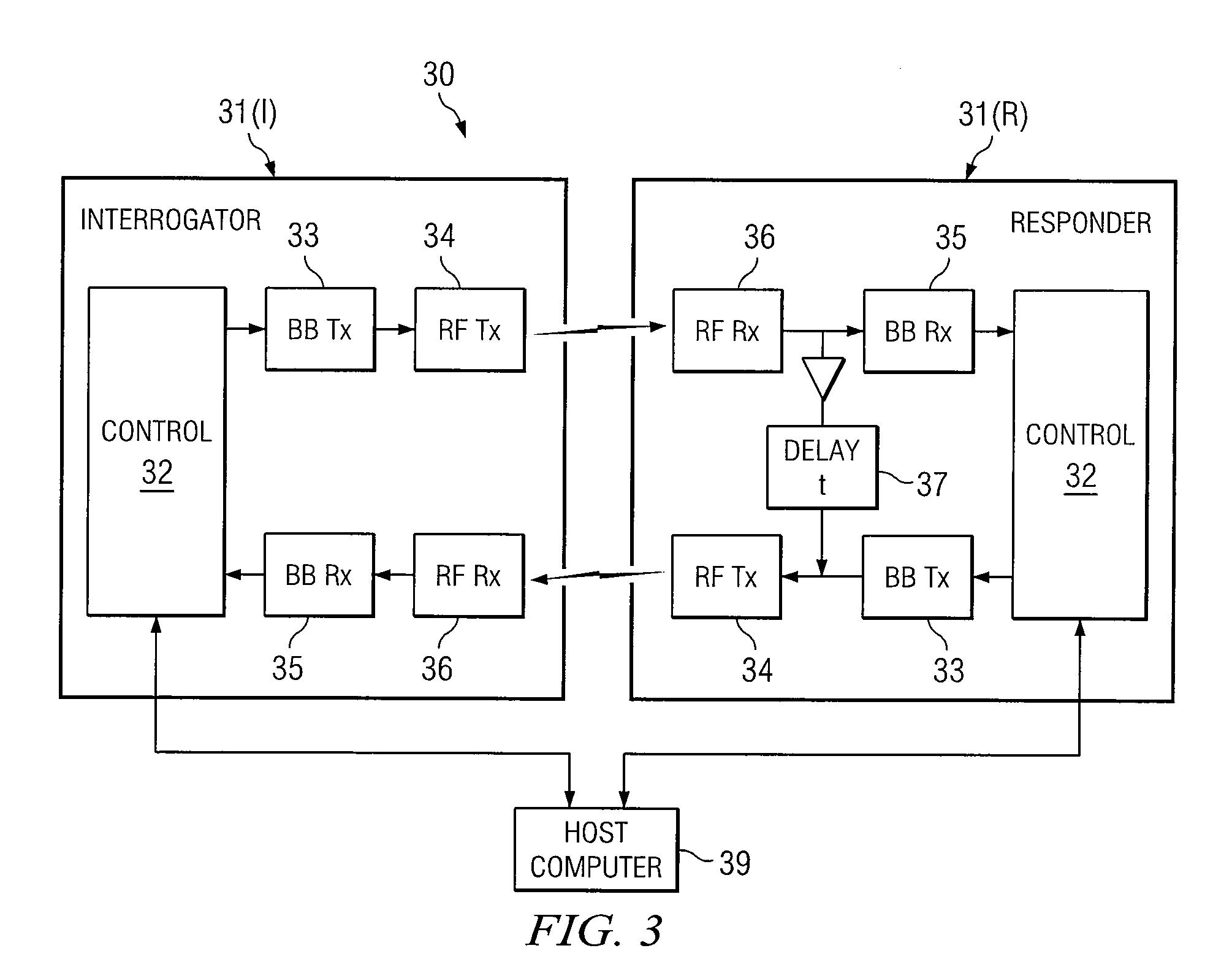
A system and method for monitoring topological changes in a defined area. A grid of sensors is arranged in the area, with known distances between them. The sensors communicate wirelessly with a host computer, which individually addresses each sensor to instruct that sensor to be in an interrogate mode or responder mode. When a sensor is in interrogate mode, it measures distance from a neighboring sensor using radar (continuous wave phase difference) measurements. When a sensor is in responder mode, it receives, delays, and returns a signal received from a neighboring sensor.

Description

TECHNICAL FIELD OF THE INVENTION[0001]This invention relates to distance measurement, and more particularly to using continuous wave phase measurement for such applications.BACKGROUND OF THE INVENTION[0002]Measurement of distance has been implemented with many different techniques, whose relative merits can be evaluated only within specific applications. For applications that preclude direct physical measurement, techniques based on time-of-flight of electromagnetic (EM) waves are often used.[0003]One type of EM-based system uses microwaves, as implemented by surveying instruments known as Tellurometers. These instruments precisely measure ground distances by determining the velocity of a phase-modulated, continuous microwave radio signal transmitted between two instruments operating alternately as master station and remote station.[0004]One application in which EM-based technology has been applied is that of distance measurement for topological monitoring. Many natural hazards (lan...

Claims


Application Information

Patent Timeline
Patent Type & Authority Patents(United States)
IPC IPC(8): G01S13/08G01S13/32G01S13/74G01S13/88G01S13/00G01S7/40
CPCG01S13/84G01S13/87G01S7/003G01S7/4004G01S13/88G01S2007/4082G01S7/4082
Inventor PILCHER, JR., MICHAEL EUGENECAMPION, BRIAN EARLABBOTT, BEN ALLEN
Owner SOUTHWEST RES INST
Learn More