
Magnetic recording medium, recording/reproducing apparatus, and stamper

a recording medium and stamper technology, applied in the direction of maintaining head carrier alignment, nanoinformatics, instruments, etc., can solve the problems of insufficient pressing of concave/convex parts (of the stamper) into the resin layer, difficult to form a concave/convex pattern on a magnetic recording medium with high precision, and difficulty in reliably reading magnetic signals

Inactive Publication Date: 2009-03-17
TDK CORPARATION
View PDF13 Cites 6 Cited by
  • Summary
  • Abstract
  • Description
  • Claims
  • Application Information

AI Technical Summary

Benefits of technology

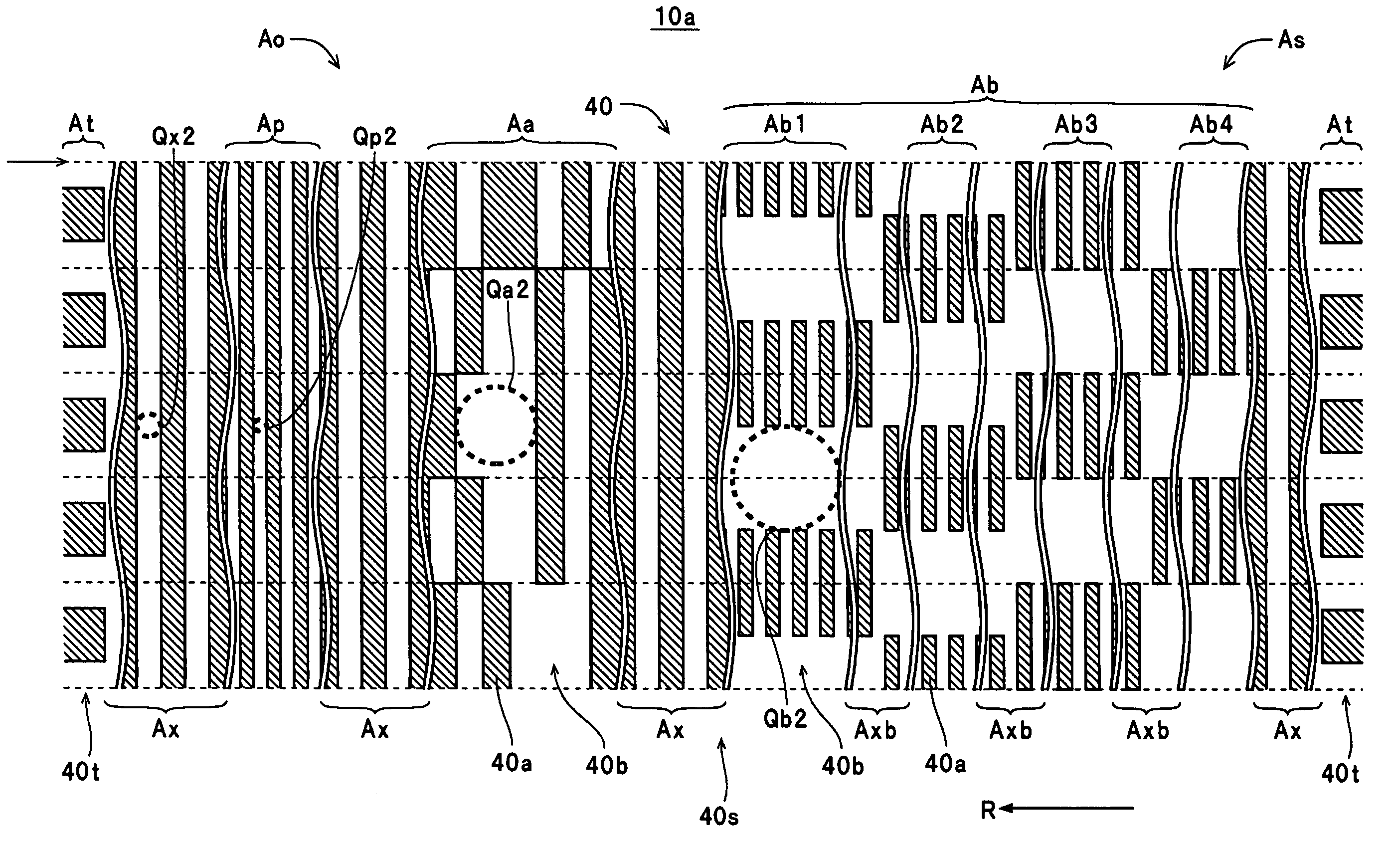
The present invention provides a magnetic recording medium with servo patterns that can be read reliably, a recording / reproducing apparatus that can track data recording tracks, and a stamper that can manufacture the magnetic recording medium. The servo patterns include a concave / convex pattern with a convex part and a concave part, and the convex part is formed so that the inscribed circle with the largest diameter is not affected by the presence of other concave / convex patterns. This avoids the use of a stamper with an excessively wide protruding end surface and ensures smooth pressing into the resin layer. The magnetic recording medium can also have multiple data recording tracks formed in a data recording region with equal or smaller distance between the tracks to avoid interference during tracking servo control. The recording / reproducing apparatus can track the data recording tracks and the burst pattern region is formed to improve the accuracy of the tracking process.

Problems solved by technology

However, when a discrete track magnetic recording medium is manufactured according to this manufacturing method, the convex parts (of the stamper) are insufficiently pressed into the resin layer.
During a process that removes resin material remaining at base parts of the concave parts in the concave / convex pattern formed in (i.e., transferred to) the resin layer, the open surfaces of the concave parts become excessively wide, and therefore it can be difficult to form a concave / convex pattern on a magnetic recording medium with high precision.
This means that with the magnetic disk 10z manufactured according to the conventional manufacturing method, due to the difficulty in forming the concave parts 41bz with the desired width during manufacturing, there is the risk of the concave parts formed in the data recording regions Atz and the servo pattern regions Asz becoming excessively wide, which can result in difficulty in reliably reading magnetic signals.

Method used


Image

  • Magnetic recording medium, recording/reproducing apparatus, and stamper
  • Magnetic recording medium, recording/reproducing apparatus, and stamper
  • Magnetic recording medium, recording/reproducing apparatus, and stamper

Examples


Embodiment Construction

[0059]Preferred embodiments of a magnetic recording medium, a recording / reproducing apparatus, and a stamper according to the present invention will now be described with reference to the attached drawings.

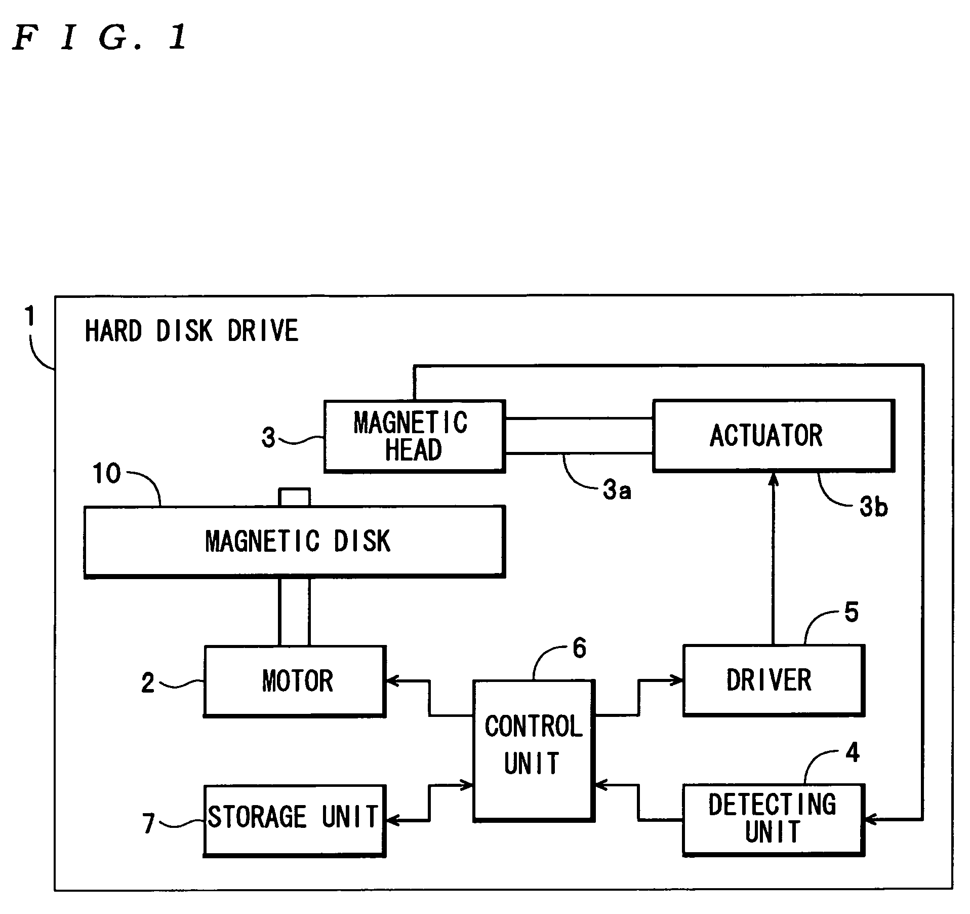
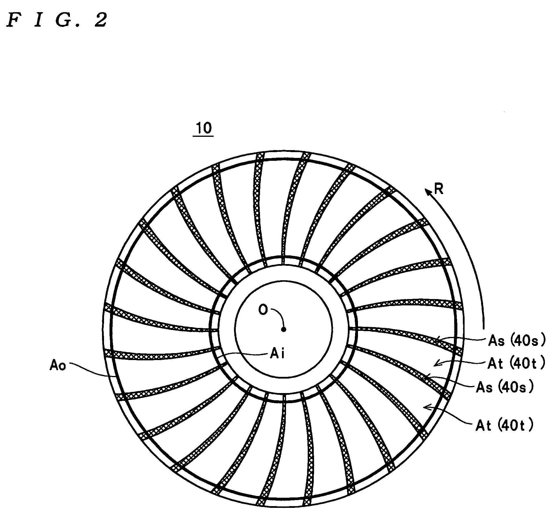
[0060]A hard disk drive 1 shown in FIG. 1 is one example of a recording / reproducing apparatus according to the present invention and includes a motor 2, a magnetic head 3, a detecting unit 4, a driver 5, a control unit 6, a storage unit 7, and a magnetic disk 10 so as to be capable of recording and reproducing various kinds of data. According to control by the control unit 6, the motor 2 rotates the magnetic disk 10 at a fixed speed, for example, 4200 rpm. The magnetic head 3 is attached to an actuator 3b via a swing arm 3a and is caused to move above the magnetic disk 10 by the actuator 3b during the recording and reproducing of data on the magnetic disk 10. Also, the magnetic head 3 carries out the reading of servo data from a servo pattern region As of the magnetic disk 10 (see...


PUM

PropertyMeasurementUnit
lateral sizeaaaaaaaaaa
thicknessaaaaaaaaaa
thicknessaaaaaaaaaa

Abstract

On a magnetic recording medium, a servo pattern is formed in a servo pattern region on at least one surface of a substrate by a concave / convex pattern including a convex part, at least protruding end part of which is formed of magnetic material, and a concave part. The servo pattern region includes an address pattern region and a burst pattern region, wherein the convex part is formed in the servo pattern region so that a larger of an inscribed circle with a largest diameter out of inscribed circles on an open surface of the concave part formed in the address pattern region and an inscribed circle with a largest diameter out of inscribed circles on an open surface of the concave part formed in the burst pattern region is an inscribed circle with a largest diameter out of inscribed circles on an open surface of the concave part formed in the servo pattern region.

Description

BACKGROUND OF THE INVENTION[0001]1. Field of the Invention[0002]The present invention relates to a magnetic recording medium where a servo pattern is formed by a concave / convex pattern in a servo pattern region, a recording / reproducing apparatus equipped with the magnetic recording medium, and a stamper for manufacturing the magnetic recording medium.[0003]2. Description of the Related Art[0004]The specification of U.S. Pat. No. 5,772,905 discloses a nanoimprint lithography method (an imprint method that forms a concave / convex pattern of nanometer size: hereinafter simply “imprint method”) that forms a concave / convex pattern of nanometer size on a substrate by pressing a stamper on which a concave / convex pattern of nanometer size is formed into a resin layer on the substrate to transfer the concave / convex pattern of the stamper to the resin layer during a manufacturing process of a semiconductor element, an information recording medium, or the like. In this imprint method, first a s...

Claims


Application Information

Patent Timeline
Patent Type & Authority Patents(United States)
IPC IPC(8): G11B5/86G11B23/02
CPCB82Y10/00G11B5/59633G11B5/74G11B5/743G11B5/855G11B5/82
Inventor SOENO, YOSHIKAZUSHIMAKAWA, KAZUYA
Owner TDK CORPARATION
Learn More