Transmission control method and system

Inactive Publication Date: 2009-03-17
NTT DOCOMO INC
View PDF6 Cites 125 Cited by
  • Summary
  • Abstract
  • Description
  • Claims
  • Application Information

AI Technical Summary

Benefits of technology

[0042]The present invention enables an optimum determination as to whether an acknowledgement received at a sender device pertains to an original data segment or to a retransmitted data segment without increasing the

Problems solved by technology

However, while this method ensures data transmission reliability it inhibits efficiency.
If data flow is suspended when a sliding window method is being employed, due to, for example, a break in wireless communication or congestion in a system, transmitted data segments may either be lost in the system or need to be stored temporarily in a node in the network until data communication is restored.
Especially, deterioration is more likely to happen in a wireless communication environment.
However, if communication disruption persists for a relatively long time, and a timeout occurs at a sender device for a transmitted data segment, the sender device retransmits a first data segment from among data segments that have thus far been transmitted but that have not been acknowledged.
This gives rise to a problem that the sender device is unable to determine whether an acknowledgment received pertains to an originally transmitted or to a retransmitted data segment, and reverts to a state where it is determined that the original data segment failed to reach the receiver device.
That is, when data s

Method used


Image

  • Transmission control method and system
  • Transmission control method and system
  • Transmission control method and system

Examples


first embodiment

A. First Embodiment

[0055]1. Configuration

[0056]Configuration of Communication System 1:

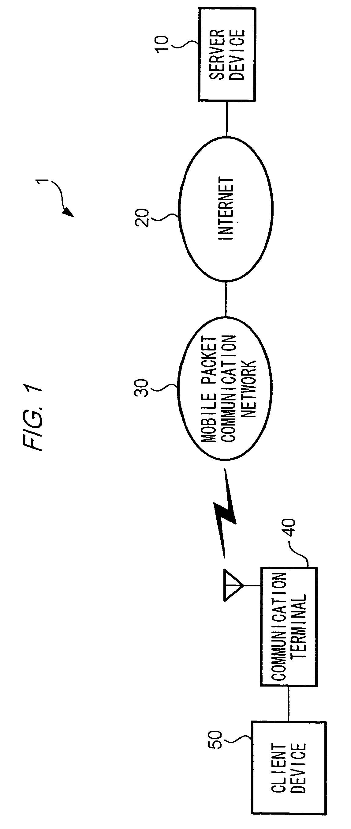
[0057]FIG. 1 is a block diagram illustrating a configuration of a communication system 1 according to a first embodiment of the present invention.

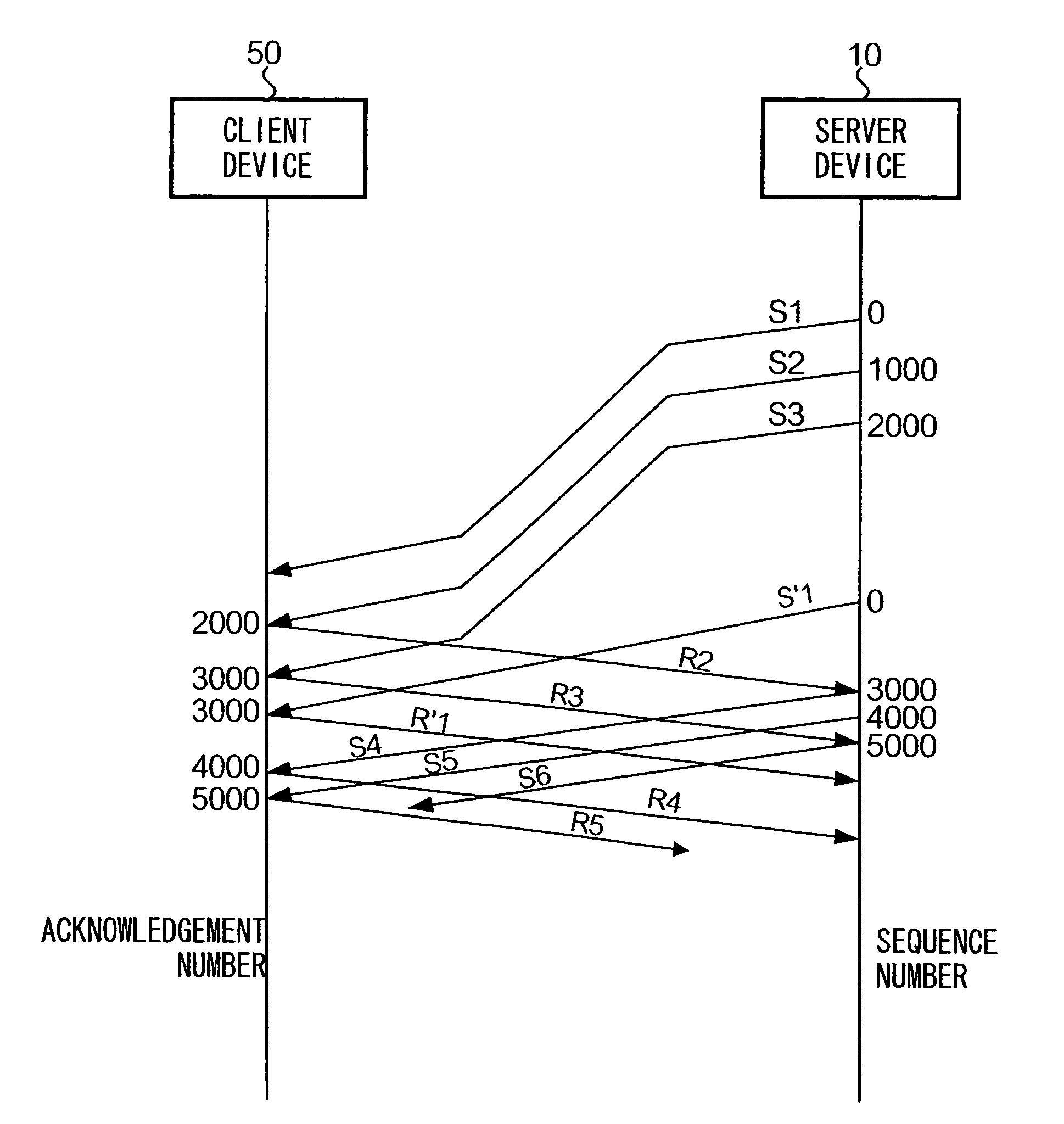
[0058]A communication terminal 40 is connected to a client device 50 and performs communications with client device 50. A mobile packet communication network 30 provides packet communication services to communication terminals 40 served by the network 30. Server device 10 performs packet communication with client device 50 via the Internet 20, mobile packet communication network 30, and communication terminal 40. It is assumed in the present embodiment that TCP (Transmission Control Protocol) is used to perform packet communications, thereby transmitting data segments.

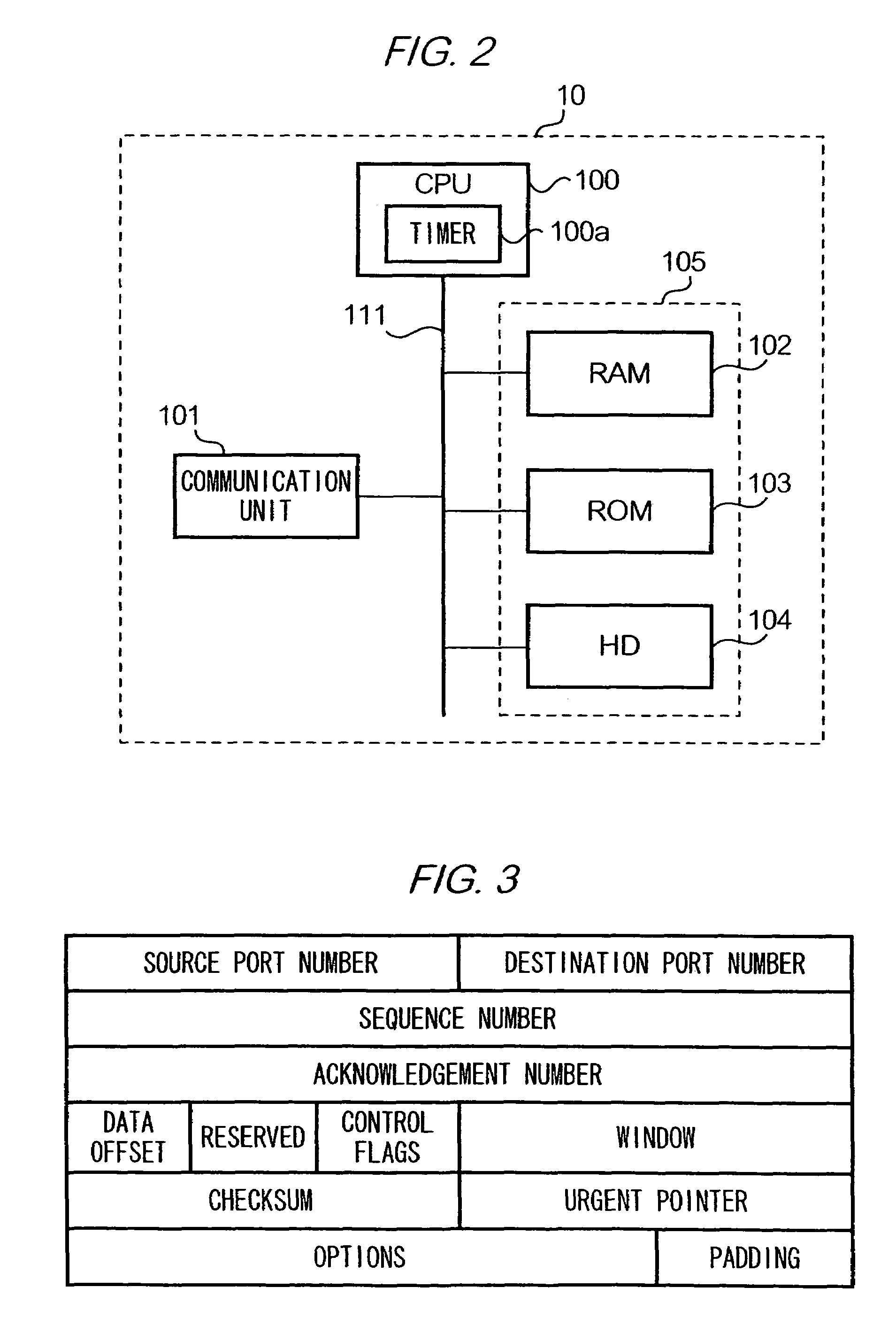
[0059]Configuration of Server Device 10:

[0060]Next, a description will be given of a configuration of server device 10. Server device 10 is configured in the same way as a standard computer...

second embodiment

B. Second Embodiment

[0093]Next, description will be given of another example of performing packet communications between server device 10 and client device 50. Hereinafter, a description of the same components as the first embodiment will be omitted. Also, like components are described with like reference numerals being assigned.

[0094]1. Configuration

[0095]Configuration of Server Device 10:

[0096]A description will be given only of those configurations relating to the present embodiment.

[0097]ROM 103 of server device 10 stores a program for causing CPU 100 to perform a data segment transmission control process. The process will be described in detail in the following, and it should be noted that those portions that are the same as those of the first embodiment will not be described here.

[0098]In the present embodiment, in transmitting data segments to client device 50, CPU 100 performs congestion control in addition to utilizing the sliding window method described in relation to the ...


PUM


Abstract

Upon receiving an acknowledgement after retransmission of a data segment, an acknowledgement number contained in the acknowledgement is compared with an acknowledgment number expected to be contained in an acknowledgement pertaining to the retransmitted data segment. When the former is larger than the latter, it is determined that the acknowledgement pertains to a data segment that was originally transmitted.

Description

TECHNICAL FIELD[0001]The invention relates to a technique for controlling retransmission of data in a communication network.BACKGROUND ART[0002]Devices that use TCP (Transmission Control Protocol) for transmitting and receiving data are now commonly employed. TCP is a protocol used under the OSI (Open Systems Interconnection) Reference Model, and is used when data streamed from an upper layer are divided into data segments for transmission from a sender device to a receiver device. TCP ensures reliable streaming of ordered data segments to a receiver device. Specifically, a number (hereinafter referred to as “a sequence number”) is allocated to each data segment in a data sequence to indicate an order of the data segment in the data sequence. A sender device allocates a sequence number to a header of each data segment to be transmitted, and also initializes a timer when the data segment is transmitted. If there is no acknowledgement from the receiver device of receipt of a transmitt...

Claims


Application Information

Patent Timeline
IPC IPC(8): H04L12/26H04L12/56H04L1/16H04L1/18H04L29/06
CPCH04L1/1621H04L1/187H04L1/188H04L29/06H04L69/161H04L69/163H04L1/1809H04L69/16H04L9/40
Inventor MIYAKE, MOTOHARUINAMURA, HIROSHITAKAHASHI, OSAMU
Owner NTT DOCOMO INC
Why Eureka
Try Eureka