X-ray diagnosis apparatus

a technology of x-ray diagnosis and x-ray, which is applied in the field of medical image processing apparatus, can solve the problems of taking a long time to move a catheter to a target, not being able to grasp the complicated structure of a blood vessel, and not being able to find optimal projection angles

Inactive Publication Date: 2009-03-17
TOSHIBA MEDICAL SYST CORP
View PDF16 Cites 42 Cited by
  • Summary
  • Abstract
  • Description
  • Claims
  • Application Information

AI Technical Summary

Benefits of technology

[0010]It is an object of the present invention to provide an image which effectively supports an operator in grasping the 3D structure of a blood vessel in a medical image processing apparatus.

Problems solved by technology

The power of expression of contrast images and blood vessel extraction images is not sufficient to grasp the complicated structure of a blood vessel.
For this reason, it may take much time to move a catheter to a target.
In addition, it may take much time to search for optimal projection angles, or radiography may need to be repeated many times at various projection angles to obtain detailed depth information.
In this case, X-rays with which these outside portions are irradiated will cause unnecessary exposure to X-rays.

Method used


Image

  • X-ray diagnosis apparatus
  • X-ray diagnosis apparatus
  • X-ray diagnosis apparatus

Examples


first embodiment

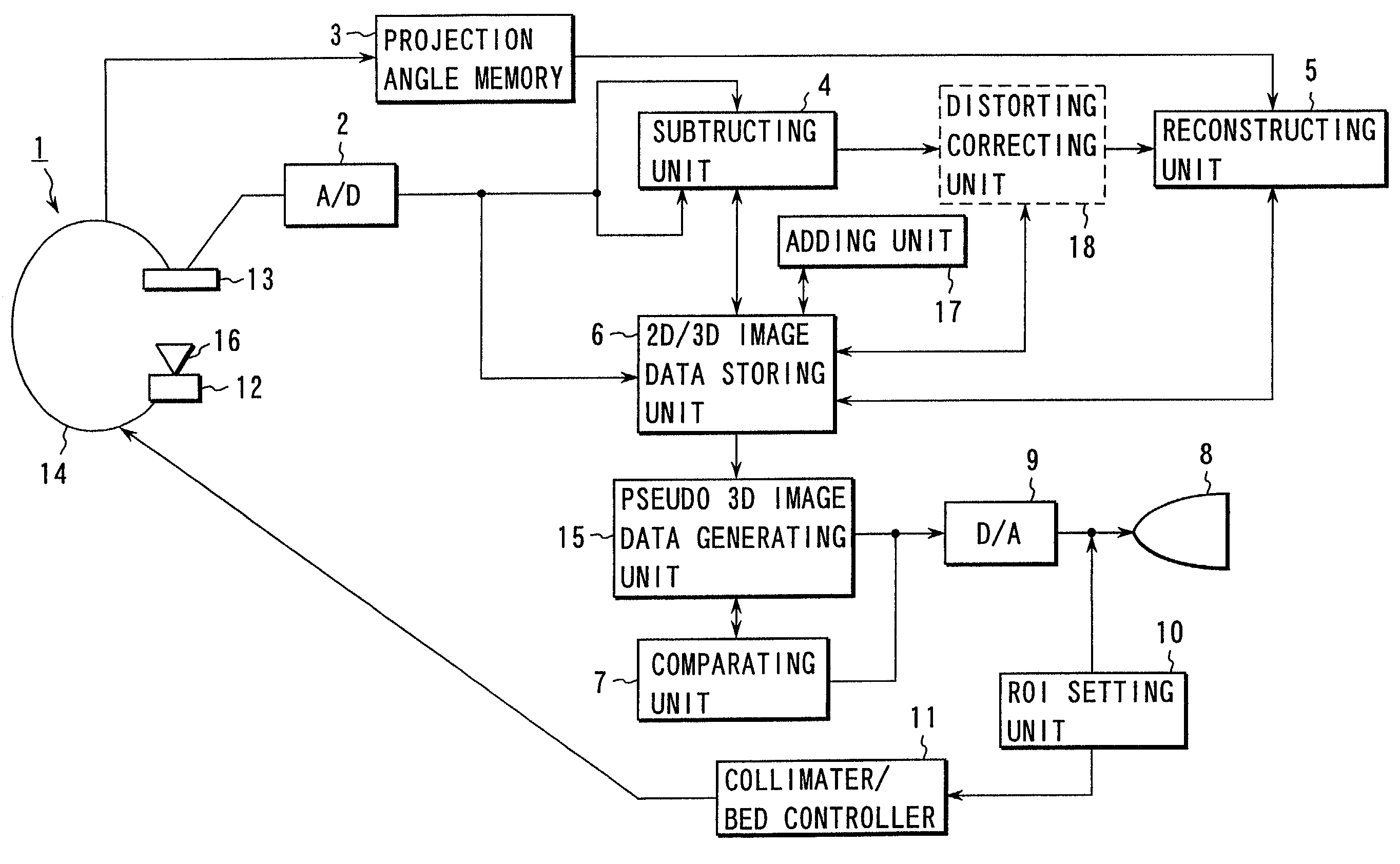
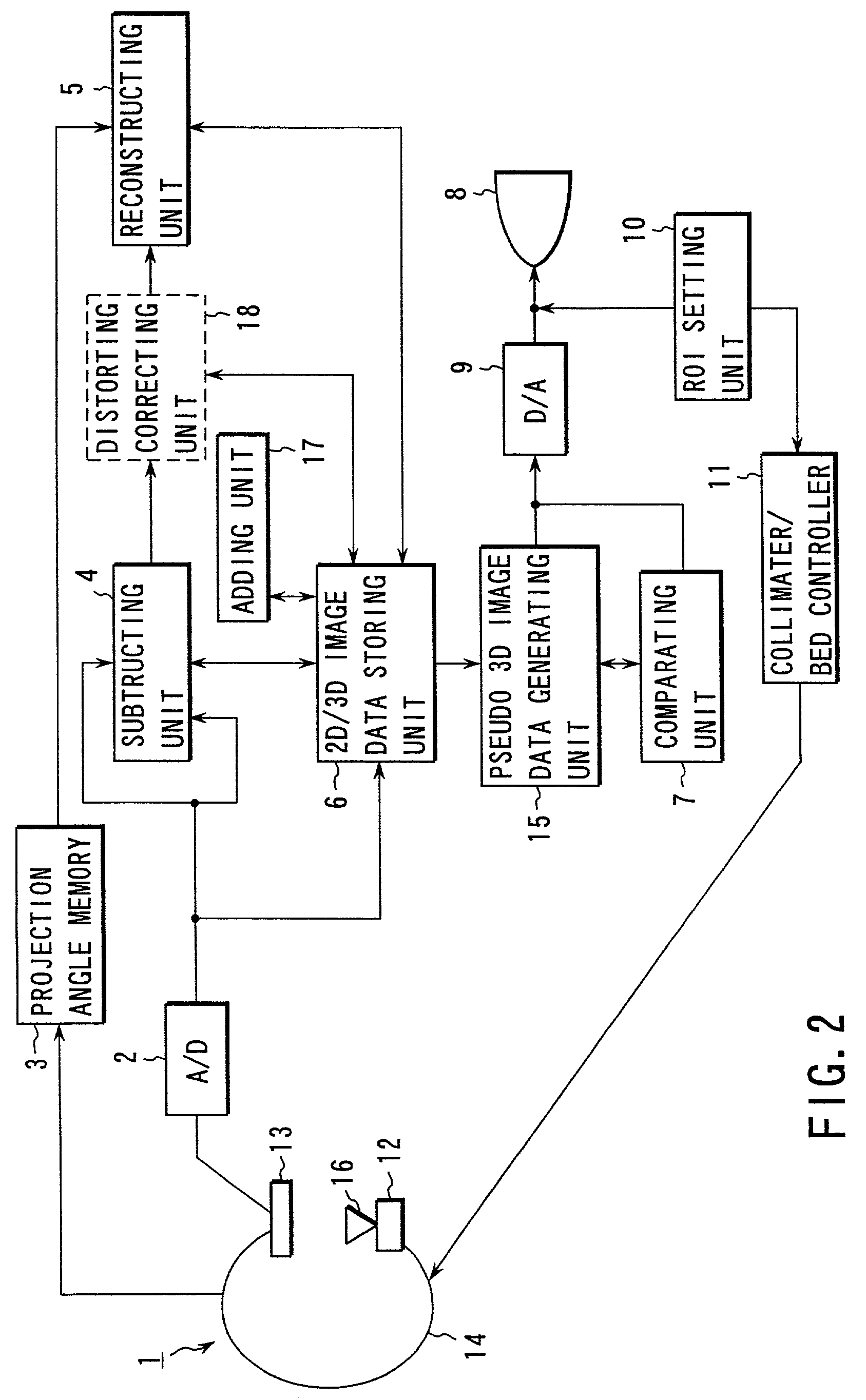
[0031]As shown in FIG. 2, the X-ray diagnosis apparatus according to the first embodiment has a radiography unit 1. The radiography unit 1 includes an arcuated arm 14 capable of rotating about three axes including the body axis of a subject, an X-ray tube 12 mounted on one end of the arcuated arm 14, an X-ray collimator 16 mounted in the X-ray window of the X-ray tube 12, and a camera system 13 mounted on the other end of the arcuated arm 14. For the sake of descriptive convenience, a rotational angle about the body axis of the subject corresponds to a projection angle. This projection angle data is stored in a projection angle memory 3. The camera system 13 is comprised of an image intensifier, optical system, and TV camera. The camera system 13 may be a planar X-ray detector constituted by solid image sensing elements, each having a scintillator and photodiode, arrayed in the form of a matrix.

[0032]An A / D converter 2 converts an analog video signal output from the camera system 13...

second embodiment

[Modification of Second Embodiment]

[0093]In the second embodiment described above, a road map is generated every time the projection angle changes. In a region where a change in projection angle (translation) is small, a road map may be translated in accordance with a change in projection angle. In addition, in a region where a change in projection angle is small, since a change in load map with a change in angle is small as compared with a change in road map with position movement, a change in projection angle can be properly coped with to a certain degree without changing a road map. A road map is therefore computed and generated again only when the projection position or angle at which the previous road map was generated changes beyond a predetermined range. In a region where a change in projection position or angle is small, a change in projection angle can be properly coped with by the previous road map without generating any new road map.

third embodiment

[0094]An X-ray diagnosis apparatus according to the third embodiment of the present invention will be described next. The same reference numerals as in the first and second embodiments denote the same parts in the third embodiment, and a detailed description thereof will be omitted. When a road map is generated according to the procedure in the second embodiment, blood vessels overlap depending on the projection angle. This may make it difficult to identify a target blood vessel structure. The third embodiment is made to solve this problem.

[0095]FIG. 12 shows the apparatus arrangement of the third embodiment, in which a pseudo 3D image data generating unit 50 extracts a target region from the 3D image data stored in an image memory 6 by the above simple threshold processing, region-growing method, or the like. The surface structure is then shaded. The resultant data is converted into an analog signal by D / A converter 52 to be displayed on a displaying unit 53. By observing this pseu...


PUM


Abstract

In a storing unit of a medical image processing apparatus, first 3D image corresponding to a first period and second 3D image data corresponding to a second period are stored. The first 3D image data corresponds to a period before contrast agent injection operation and / or therapeutic operation. The second 3D image data corresponds to a period after the contrast agent injection operation and / or therapeutic operation. A 3D subtracting unit subtracts the first 3D image data from the second 3D image data. In 3D subtraction image data, a portion having undergone a change due to contrast agent injection operation and / or therapeutic operation is emphasized. A pseudo 3D image data generating unit generates pseudo 3D image data on the basis of 3D subtraction image data. A displaying unit displays the pseudo 3D image data.

Description

CROSS-REFERENCE TO RELATED APPLICATIONS[0001]This application is a divisional application of, and claims priority to, U.S. patent application Ser. No. 09 / 488,673 filed Jan. 21, 2000 now U.S. Pat. No. 6,721,590, the entire contents of which are incorporated herein by reference.BACKGROUND OF THE INVENTION[0002]The present invention relates to a medical image processing apparatus for supporting an examination, diagnosis, and therapy using a catheter and the like.[0003]According to a conventional therapeutic method for aneurysms, an incision is surgically made in a patient's body to expose a morbid portion (aneurysm), and the neck of the exposed aneurysm is fastened with a clip to prevent blood from flowing into the aneurysm.[0004]Recently, however, a great deal of attention has been given to a low-invasive therapeutic method represented by IVR (InterVentional Radiology). The low-invasive therapeutic method is also applied to a therapy for aneurysms. For example, a catheter is inserted ...

Claims


Application Information

Patent Timeline
Patent Type & Authority Patents(United States)
IPC IPC(8): A61B6/00A61B5/055G16H30/40
CPCA61B6/466A61B6/469A61B6/481A61B6/504G06F19/321A61B5/055A61B6/12G06T2211/404G06F19/3468G16H30/40
Inventor OHISHI, SATORUAOKI, KUNIO
Owner TOSHIBA MEDICAL SYST CORP
Why Eureka
Try Eureka