
Graphical data flow programming environment with first model of computation that includes a structure supporting second model of computation

a programming environment and data flow technology, applied in the field of graphical programming, can solve the problems of user programming skills and ability to interact with the computer system often becoming a limiting factor in the achievement of optimal utilization of the computer system, complex task of programming a computer system to model or implement a process, and user's inability to fully grasp techniques

Active Publication Date: 2009-03-17
NATIONAL INSTRUMENTS
View PDF17 Cites 97 Cited by
  • Summary
  • Abstract
  • Description
  • Claims
  • Application Information

AI Technical Summary

Benefits of technology

Enables the development of complex applications by allowing different models of computation to coexist, improving the ability to handle multi-rate systems and simulations, and enhancing the utility of graphical programming in areas like signal processing and control systems.

Problems solved by technology

When traditional text-based programming environments are used, the user's programming skills and ability to interact with the computer system often become a limiting factor in the achievement of optimal utilization of the computer system.
There are numerous subtle complexities which a user must master before he can efficiently program a computer system in a text-based environment.
The task of programming a computer system to model or implement a process often is further complicated by the fact that a sequence of mathematical formulas, steps or other procedures customarily used to conceptually model a process often does not closely correspond to the traditional text-based programming techniques used to program a computer system to model such a process.
Since a user often is not fully proficient in techniques for programming a computer system in a text-based environment to implement his solution, the efficiency with which the computer system can be utilized often is reduced.
There are numerous applications where this restriction may limit the utility or applicability of the program.
1. The breaking of wiring cycles is accomplished by using control / local pairs or shift registers on the top level diagram. In the case of shift registers, the resulting diagram does not look like a control block diagram. In either case, the user is exposed to a situation where there are values from the current iteration as well as the previous iteration. The cosmetic problem could be alleviated by a “free rangeshift register. The problem of data from two distinct iterations appearing simultaneously on the diagram is problematic, however, and may be difficult to solve.
2. The handling of hierarchies in the model nodes is problematic in GSIM. It can be shown that all feedback cycles must be broken on the top level diagram. This in turn implies that a subsystem that is written as a subVI cannot contain a feedback cycle. Elements of a complex model that would logically be encapsulated (e.g. the engine model is a subsystem of the whole-car model) therefore cannot be put into a subVI.
3. The implementation of certain types of ordinary differential equation (ODE) integrators is difficult or impossible in GSIM. Falling into this category are implicit solvers, multi-stage methods, and adaptive step-size methods. The problem in all of these cases is that these integration methods require the diagram specifying the differential equation to be evaluated multiple times per single “time step” of the solver. This introduces problems at source and sink nodes as well as in nodes that have memory (e.g., a filter.)
G, however, based on a homogenous dynamic model of computation, is restricted to single-rate execution, and thus there is currently no mechanism in LabVIEW to efficiently specify multi-rate systems.
Users of such systems based on a homogenous data flow model of computation may deal with this limitation by 1) using different sized arrays for the inputs and the outputs of each VI, which is cumbersome and an inefficient use of memory; or 2) using independent loops running at different rates communicating through local or global variables, also tedious and cumbersome for the user.
In general, embedded digital signal processors (DSPs) have limited memory and processing power, and so the inclusion of a dynamic scheduler may not be feasible.
However, the homogenous dynamic model of computation used by G utilizes dynamic scheduling and so may require a dynamic scheduler, which may limit the utility or application of LabVIEW graphical programs in these and other platforms and applications.

Method used


Image

  • Graphical data flow programming environment with first model of computation that includes a structure supporting second model of computation
  • Graphical data flow programming environment with first model of computation that includes a structure supporting second model of computation
  • Graphical data flow programming environment with first model of computation that includes a structure supporting second model of computation

Examples


Embodiment Construction

Incorporation by Reference

[0064]The following references are hereby incorporated by reference in their entirety as though fully and completely set forth herein:

[0065]U.S. Pat. No. 4,914,568 titled “Graphical System for Modeling a Process and Associated Method,” issued on Apr. 3, 1990.

[0066]U.S. Pat. No. 5,481,741 titled “Method and Apparatus for Providing Attribute Nodes in a Graphical Data Flow Environment”.

[0067]U.S. Pat. No. 6,219,628 titled “System and Method for Converting Graphical Programs Into Hardware Implementations” filed Mar. 22, 2000.

[0068]U.S. Pat. No. 6,173,438 titled “Embedded Graphical Programming System” filed Aug. 18, 1997.

[0069]U.S. Pat. No. 6,219,628 titled “System and Method for Configuring an Instrument to Perform Measurement Functions Utilizing Conversion of Graphical Programs into Hardware Implementations,” filed Aug. 18, 1997.

[0070]U.S. Patent Application Publication No. 20010020291 (Ser. No. 09 / 745,023) titled “System and Method for Programmatically Genera...


PUM


Abstract

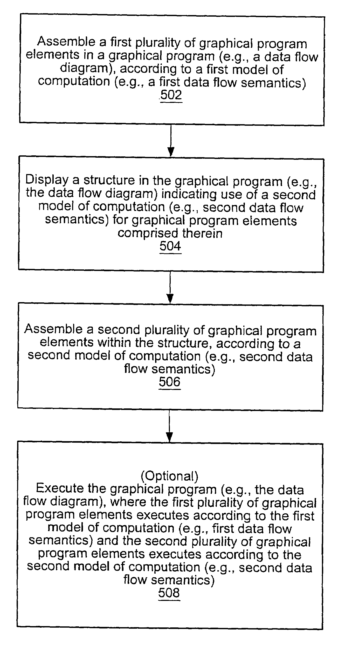
System and method for creating a graphical program that uses multiple models of computation (MoC). A first plurality of graphical program elements is assembled in a graphical program in response to first input, where the assembled first plurality of graphical program elements have a first MoC. A structure is displayed in the graphical program indicating use of a second MoC for graphical program elements comprised within the interior of the structure. A second plurality of graphical program elements is assembled within the structure in response to second input, where the assembled second plurality of graphical program elements have the second MoC. The graphical program is executable to perform a function, for example, by executing the assembled first plurality of graphical program elements in accordance with the first model of computation, and executing the assembled second plurality of graphical program elements in accordance with the second model of computation.

Description

PRIORITY DATA[0001]This application claims benefit of priority of U.S. Provisional Application Ser. No. 60 / 571,205 titled “Graphical Data Flow Programming Environment with First Model of Computation that Includes a Structure Supporting Second Model of Computation” filed May 14, 2004, whose inventors were Gregory O. Morrow, John C. Limroth, Jeffrey L. Kodosky, Steven W. Rogers, Kevin Hogan, and Hugo A. Andrade.FIELD OF THE INVENTION[0002]The present invention relates to the field of graphical programming, and more particularly to a graphical data flow programming environment with a first model of computation that includes a structure supporting a second model of computation.DESCRIPTION OF THE RELATED ART[0003]Traditionally, high level text-based programming languages have been used by programmers in writing application programs. Many different high level text-based programming languages exist, including BASIC, C, C++, Java, FORTRAN, Pascal, COBOL, ADA, APL, etc. Programs written in t...

Claims


Application Information

Patent Timeline
Patent Type & Authority Patents(United States)
IPC IPC(8): G06F9/44
CPCG06F8/34
Inventor MORROW, GREGORY O.LIMROTH, JOHN C.KODOSKY, JEFFREY L.ROGERS, STEVEN W.HOGAN, KEVINANDRADE, HUGO A.
Owner NATIONAL INSTRUMENTS
Learn More