Foot pressure detection device

a detection device and foot technology, applied in the field of foot pressure detection devices, can solve the problems of difficult to remain conscious of the need, difficult for most people to remember, and the risk of secondary injuries or trauma, and achieve the effect of simple construction and use, and reduced manufacturing costs

Inactive Publication Date: 2009-03-24
CONCEPTS & MEDICINE
View PDF8 Cites 9 Cited by
  • Summary
  • Abstract
  • Description
  • Claims
  • Application Information

AI Technical Summary

Benefits of technology

[0004]Recognizing the need for the development of improved pressure monitoring under or within, for example, a cast, boot, shoe, mat, sock, insole or other lower extremity immobilization or protective device, the present invention is generally directed to satisfying the needs set forth above and overcoming these and other disadvantages with prior art devices and to providing a device that is comfortable or at least not uncomfortable when used.
[0005]An illustrative, but not inclusive, listing of advantages that may now be realized in various exemplary embodiments of the present invention include: providing a pressure detection device that is simple to construct and use and whose manufacturing costs my be kept to a minimum; providing a pressure detection device that will detect that a threshold of pressure has been applied to the bottom of a cast, boot, shoe, or other lower extremity immobilization or protective device; and providing a pressure detection device that will alert both the patient and health care provider detect that pressure has been applied to the bottom of a cast, boot, shoe, or other lower extremity immobilization or protective device, such that, for instance: (1) appropriate counseling may be undertaken, (2) further instruction or physical therapy can be provided to the patient, or (3) the protective device may be appropriately augmented.

Problems solved by technology

A recurring problem with recovery from an injury in a lower extremity, such as a leg or foot, is the risk of secondary injuries or trauma.
However, even if a patient is generally aware and exercising care not to place undue pressure on a recovering extremity, it is difficult for most people to remember how much a given threshold weight feels like when using their legs, and even the best of patients find it difficult to remain conscious of the need to avoid more than that threshold, avoid missteps or loss of balance, or the like, all events which could lead to too much pressure being exerted.
For example, their designs are: (1) too complex, (2) too costly, (3) and fail to fully record and document all incidents in which too much pressure has been exerted.

Method used


Image

  • Foot pressure detection device
  • Foot pressure detection device

Examples


Embodiment Construction

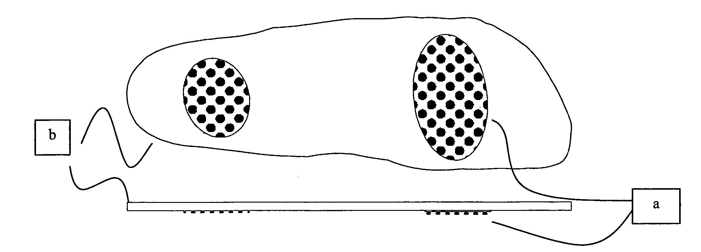
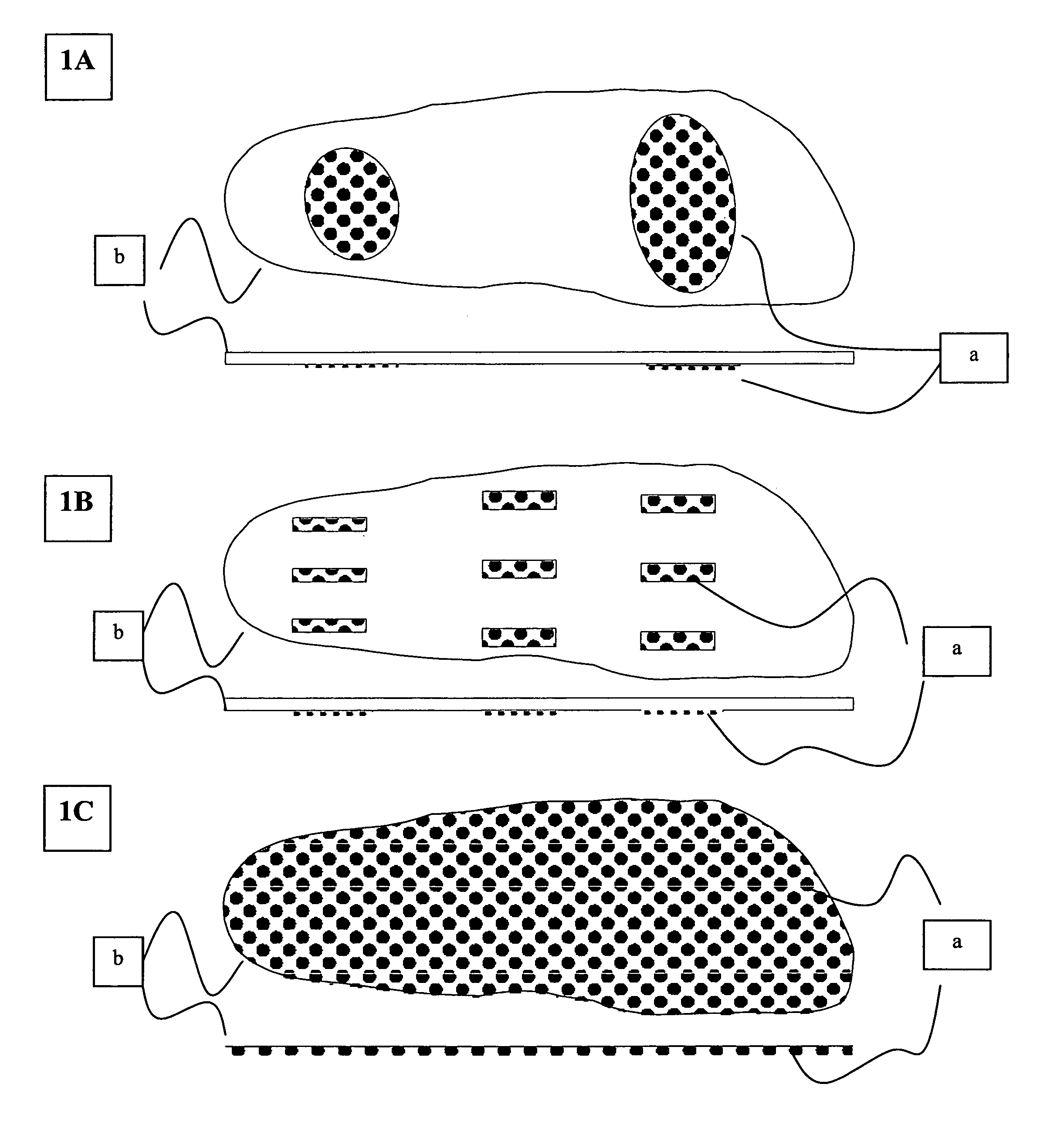
[0009]In the following, FIGS. 1A-1C diagrammatically illustrate various embodiments of the present invention. These figures respectively depict illustrative bottom and right side cross-sectional views each of different passive foot pressure detection devices in accordance with embodiments of the present invention. In this and the other figures, the symbol “•” is used to schematically represent pressure sensitive chambers.

[0010]In accordance with embodiments of the present invention, the pressure sensitive chambers are preferably designed to burst or otherwise release their contents at a known, e.g., pre-determined force or weight. As will be recognized by those skilled in the art, the pressure that the chambers burst depends upon the material of chambers and, for example, the thickness of the chamber walls. These parameters are well known to those skilled in the art, and are therefore not discussed herein.

[0011]The pressure sensitive chambers may be filled with air or other gases, a...


PUM


Abstract

According to a first embodiment of our invention, a monitoring device is placed above, within, or on the bottom of a cast, boot, shoe, or other lower extremity immobilization or protective device, and has one or more single or cluster of pressure sensitive chambers designed to burst at a predetermined force or weight. The pressure sensitive chambers may be filled with air, liquid, semi-liquid, or particulate material. Once properly positioned, the device serves to detect and alert one or more individuals to the fact that weight-bearing has occurred and / or that a certain amount of force has been transmitted across the bottom or other portion of the cast, boot, shoe, mat, sock, insole, or lower extremity immobilization or protective device in a setting where such pressure could be deleterious or harmful (including situations where patients are recovering from a bony fracture, tendon injury, and recent lower extremity surgery).

Description

BACKGROUND OF THE INVENTION[0001]The current invention generally relates to an apparatus for detecting force or pressure applied to the bottom of a foot and lower extremity, and more particularly, to an apparatus for detecting the application of a predetermined threshold amount of force or pressure applied to a cast, boot, shoe, mat, insole, sock, or other lower extremity immobilization or protective device, where the predetermined threshold relates to a pressure threshold that could be deleterious or harmful if exceeded (including situations where patients are recovering from a bony fracture, tendon injury, and recent lower extremity surgery).[0002]A recurring problem with recovery from an injury in a lower extremity, such as a leg or foot, is the risk of secondary injuries or trauma. As patients begin recovering, they naturally want to resume their typical routine, and in many cases the increased activity is part of their rehabilitation regime. However, even if a patient is genera...

Claims


Application Information

Patent Timeline
Patent Type & Authority Patents(United States)
IPC IPC(8): A61B5/00
CPCA43B7/00A43B7/1455A43B7/147A43B17/00A61B5/1036A61F13/045
Inventor CHIODO, CHRISTOPHER P.PARKS, BRENT G.SCHON, LEW C.CHIODO, LYNNE
Owner CONCEPTS & MEDICINE
Why Eureka
Try Eureka