
Control system for modulating water heater

a control system and water heater technology, applied in water feed control, instruments, heating types, etc., can solve problems such as undesirable swings in system temperature, on and off cycle of boilers, and fluctuation of water flow rate in primary heating loops, so as to reduce the cycle of modulating water heaters. , the effect of preventing condensation of water vapor

Active Publication Date: 2009-03-24
LOCHINVAR
View PDF15 Cites 48 Cited by
  • Summary
  • Abstract
  • Description
  • Claims
  • Application Information

AI Technical Summary

Benefits of technology

[0013]Another issue encountered in commercial heating systems is that the flow rate of the water in the primary heating loop can change frequently and by a significant amount as heating zones are turned on and off. As this flow changes, the heat load on the system typically changes with it. In prior art systems the only indication the boiler has that heat load has changed is when one of the temperature sensors detects a change in system temperature. But the change in system temperature lags significantly in time behind the change in flow rate, and causes undesirable swings in system temperature and on and off cycling of the boiler as the boiler control system attempts to correct for the change in temperature. This problem is addressed by monitoring the flow rate within the system and then utilizing an algorithm to predict the change in heat load which will result from that change in flow rate, and varying the firing rate of the boiler to correspond to the expected change in heat load. This allows the boiler to react much more quickly to changes in system demand and significantly reduces temperature swings in the system and reduces cycling of the boiler itself.
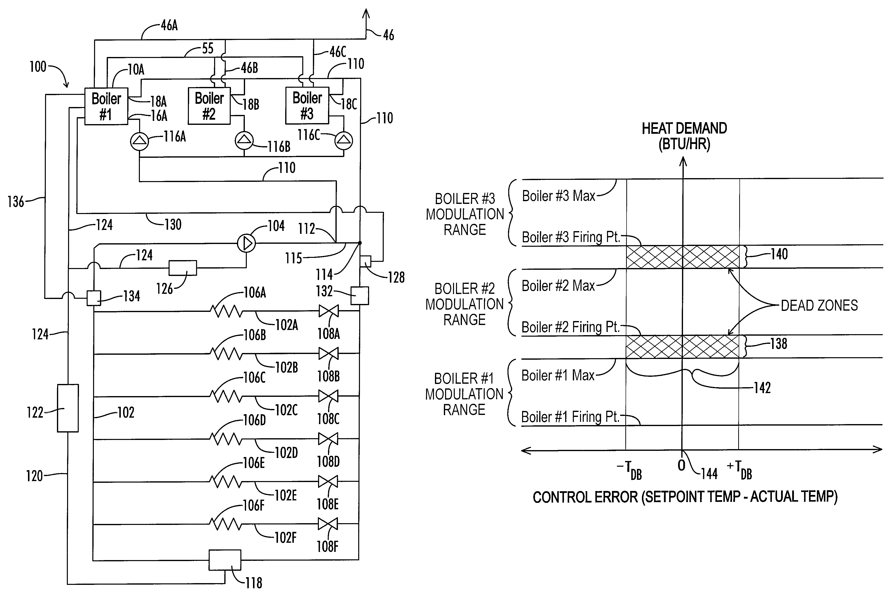
[0014]A third issue encountered in these multiple boiler systems is the problem of condensation of water vapor in exhaust flue gases. Such condensation is acidic, and therefore if condensation is expected much more expensive Category IV venting materials are required by codes, with separate flue vents for each boiler. On the other hand, if the temperature of the exhaust flue gases can be reliably controlled and maintained above a temperature at which the water vapor will condense from the exhaust gases, then much more economical Category I materials may be utilized and a common exhaust flue may be used for multiple boilers. This is particularly a problem with modulating boilers and systems of modulating boilers because as the power demands change and the power output of each boiler changes its exhaust gas temperature changes. This problem is addressed by providing an exhaust gas temperature sensor in each boiler and controlling the modulation range of each boiler during modulation so that the boiler is not allowed to operate below a minimum heat output, which is typically significantly greater than the minimum firing point for the boiler, and is high enough to maintain boiler exhaust gas temperatures at the required level. This will reduce the practical modulation range for each boiler, thus increasing the width of the deadbands noted above.
[0018]Still another object of the present invention is the provision of control systems which will reduce cycling of modulating water heaters.
[0019]Yet another object of the present invention is the provision of a control system that reduces cycling of a modulating water heater when a plurality of heaters are called upon to provide a combined heat output which falls in a deadband between the modulating range of one heater and that of the next subsequent heater.
[0020]Still another object of the present invention is the provision of a control system which allows early detection of changes in system heat load by sensing changes in water flow before those changes have had time to significantly impact water temperature.
[0021]Yet another object of the present invention is the provision of control systems for preventing condensation of water vapor from exhaust flue gases in multiple water heater systems.

Problems solved by technology

One challenge encountered with a system of modulating boilers like that just described is to minimize the cycling on and off of each boiler.
This zone, which may be referred to as a deadband or dead zone, presents unique operational problems because the second boiler cannot modulate within that range.
Another issue encountered in commercial heating systems is that the flow rate of the water in the primary heating loop can change frequently and by a significant amount as heating zones are turned on and off.
As this flow changes, the heat load on the system typically changes with it.
But the change in system temperature lags significantly in time behind the change in flow rate, and causes undesirable swings in system temperature and on and off cycling of the boiler as the boiler control system attempts to correct for the change in temperature.

Method used


Image

  • Control system for modulating water heater
  • Control system for modulating water heater
  • Control system for modulating water heater

Examples


Embodiment Construction

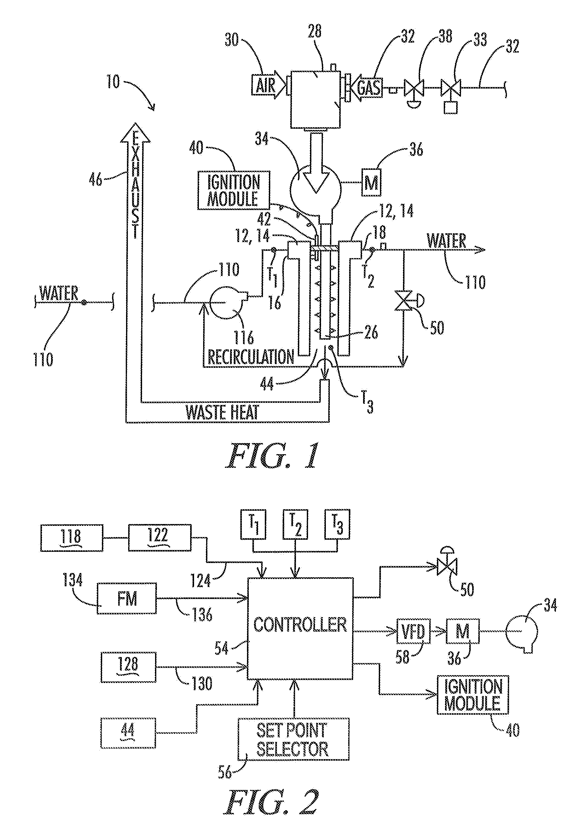
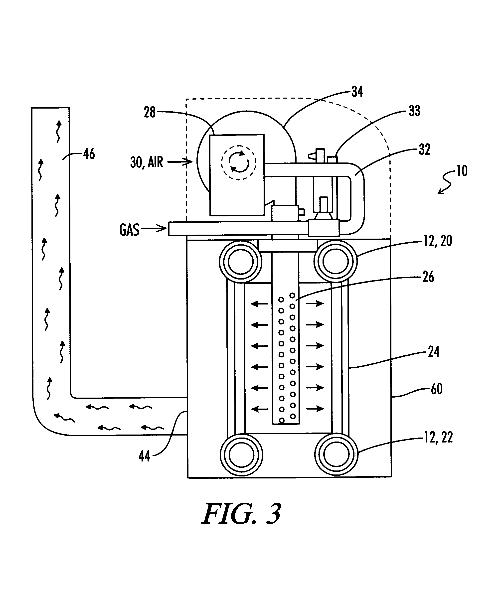
[0029]Referring now to the drawings, and particularly to FIG. 1, the water heater or boiler apparatus of the present invention is shown and generally designated by the numeral 10. As used herein, the term water heater refers to an apparatus for heating water, including both steam boilers and water heaters that do not actually “boil” the water. Much of this discussion refers to the apparatus 10 as a boiler 10, but it will be understood that this description is equally applicable to water heaters that do not boil the water. The boiler 10 includes a heat exchanger 12 having a water side 14 having a water inlet 16 and a water outlet 18.

[0030]The general construction of the heat exchanger 12 may be similar to that disclosed for example in U.S. Pat. No. 4,793,800 to Vallett et al., or that in U.S. Pat. No. 6,694,926 to Baese et al., the details of which are incorporated herein by reference. As illustrated in FIGS. 2, 8 and 9 of Vallett et al., the heat exchanger is a multiple pass exchang...


PUM


Abstract

A control system is provided for a modulated heating system including a plurality of modulating water heaters, which may be modulating boilers. A deadband control scheme provides for reduced cycling of the modulating heater when total system heat demand falls between the maximum output of one heater and the sum of the maximum output of that one point and the minimum firing point of the next subsequent heater.

Description

BACKGROUND OF THE INVENTION[0001]1. Field of the Invention[0002]The present invention relates generally to water heaters and boilers, and more particularly, but not by way of limitation, to a control system for a modulating water heater or boiler which is particularly constructed for use as one of a plurality of water heaters or boilers controlled in a cascading sequence.[0003]2. Description of the Prior Art[0004]Conventional water heater technology utilizes a burner designed to operate at a fixed flow rate of combustion air and fuel gas to the burner. Such a water heater cycles on and off in response to a control system which monitors the temperature of water in a storage tank or elsewhere in various conduits of the water supply system. One example of such a typical prior art system which is presently being marketed by the assignee of the present invention is that shown in U.S. Pat. Nos. 4,723,513 and 4,793,800 to Vallett et al., the details of which are incorporated herein by refe...

Claims


Application Information

Patent Timeline
Patent Type & Authority Patents(United States)
IPC IPC(8): F22B37/42
CPCF23N1/082F24D19/1009F23N2041/04F24D2200/043Y02B30/108F24H9/2035F23N2241/04F24H15/219F24H15/34F24H15/215F24H15/238F24H15/174F24H15/36F24H15/35F24H15/235Y02B30/00
Inventor PAINE, JOHN C.
Owner LOCHINVAR
Learn More