
Marine reversing gear assembly provided with locking device

a technology of locking device and gear assembly, which is applied in the direction of marine propulsion, vessel parts, vessel construction, etc., can solve the problems of limiting the order of the steps of attaching propeller driving parts to the ship, the inability to connect the lubricating oil circuit of the internal combustion engine to the locking mechanism member of the reduction-reversing gear, and the inability to fix the propeller driving parts. the effect of reducing the operability of the locking mechanism member and improving the efficiency of the installation

Active Publication Date: 2009-03-24
YANMAR POWER TECHNOLOGY CO LTD
View PDF8 Cites 5 Cited by
  • Summary
  • Abstract
  • Description
  • Claims
  • Application Information

AI Technical Summary

Benefits of technology

The present invention provides a marine reversing gear assembly with a locking device that is self-contained and does not require the introduction of hydraulic pressure from an internal combustion engine. The assembly includes a hydraulic pump, a forward and reverse clutch, a directional control valve, and a hydraulic actuator. The locking mechanism member is designed to unlock the output shaft by operating on the locking part using the hydraulic actuator. The assembly is easy to install and improves operability and efficiency. The locking mechanism member is dismountable and can be retrofitted to different specifications of the ship. The oil supply circuit is designed to supply high-pressure oil to the forward or reverse clutch before adjusting the pressure for use as a working oil for the hydraulic actuator, and unlocking can be conducted quickly.

Problems solved by technology

Therefore, unless both an internal combustion engine and a reduction-reversing gear are provided, connection cannot be obtained between the lubricating oil circuit in the internal combustion engine and the locking mechanism member in the reduction-reversing gear.
This limits the order of the steps of attaching the propeller driving parts to the ship.

Method used


Image

  • Marine reversing gear assembly provided with locking device
  • Marine reversing gear assembly provided with locking device
  • Marine reversing gear assembly provided with locking device

Examples


Embodiment Construction

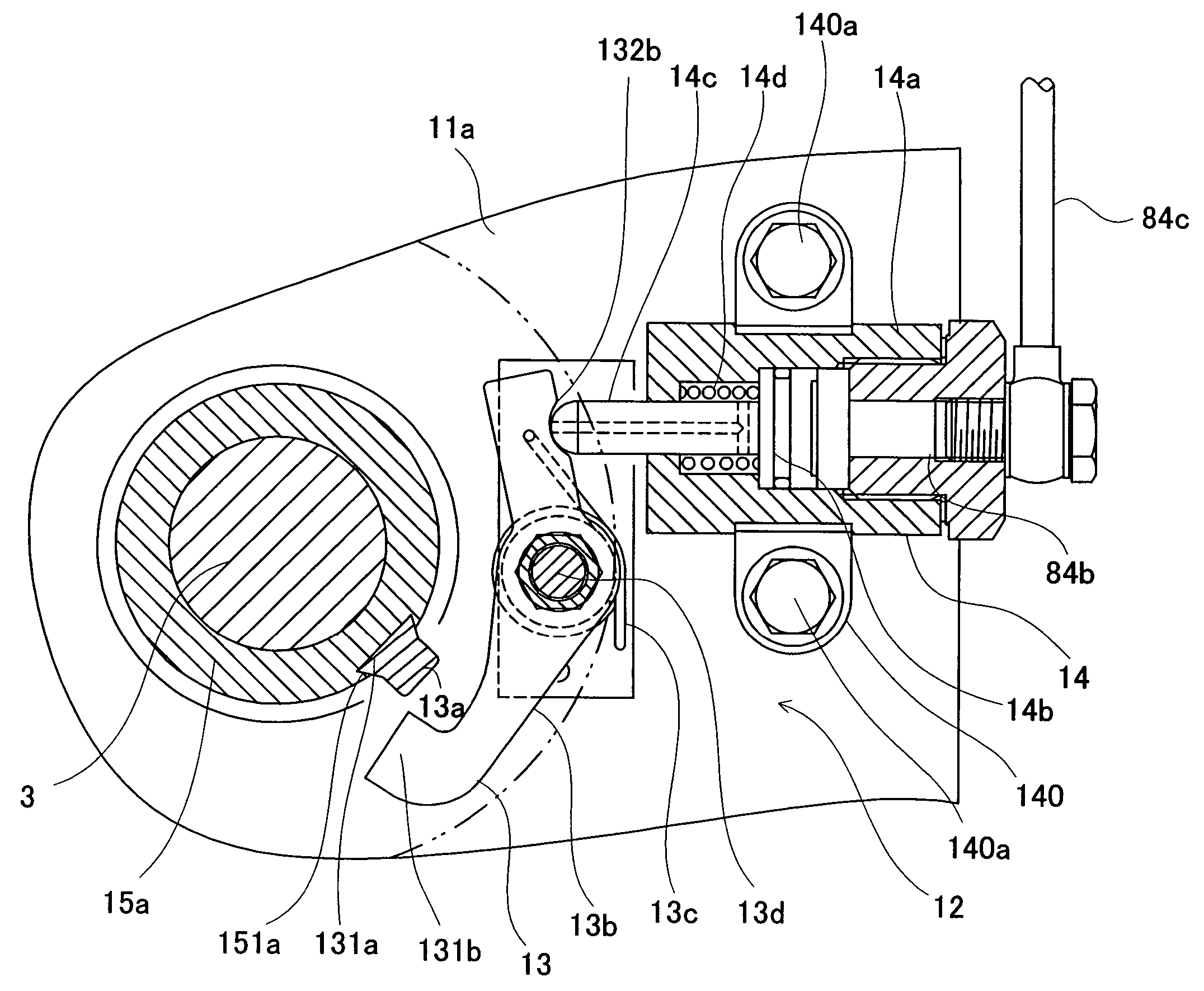
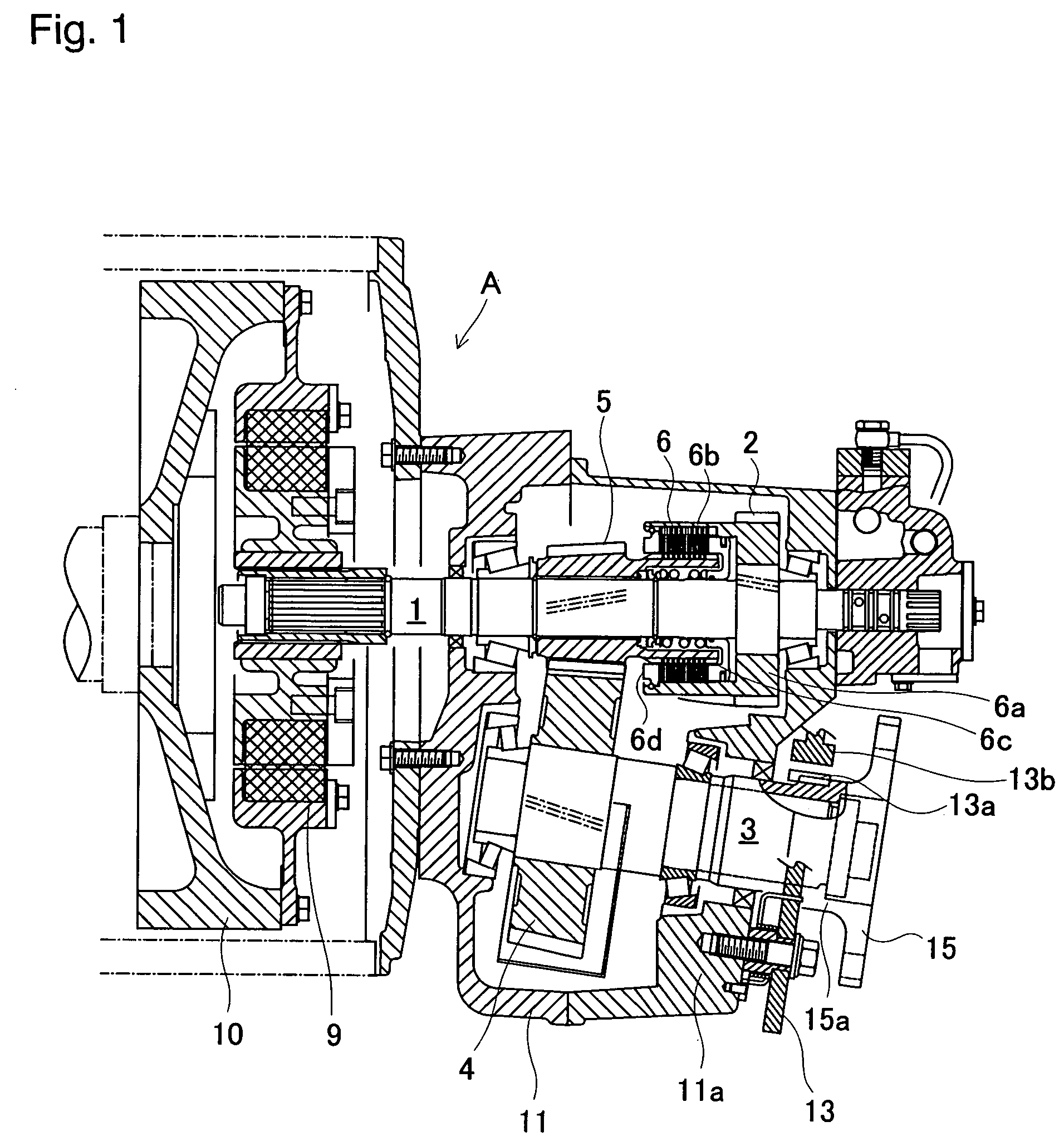
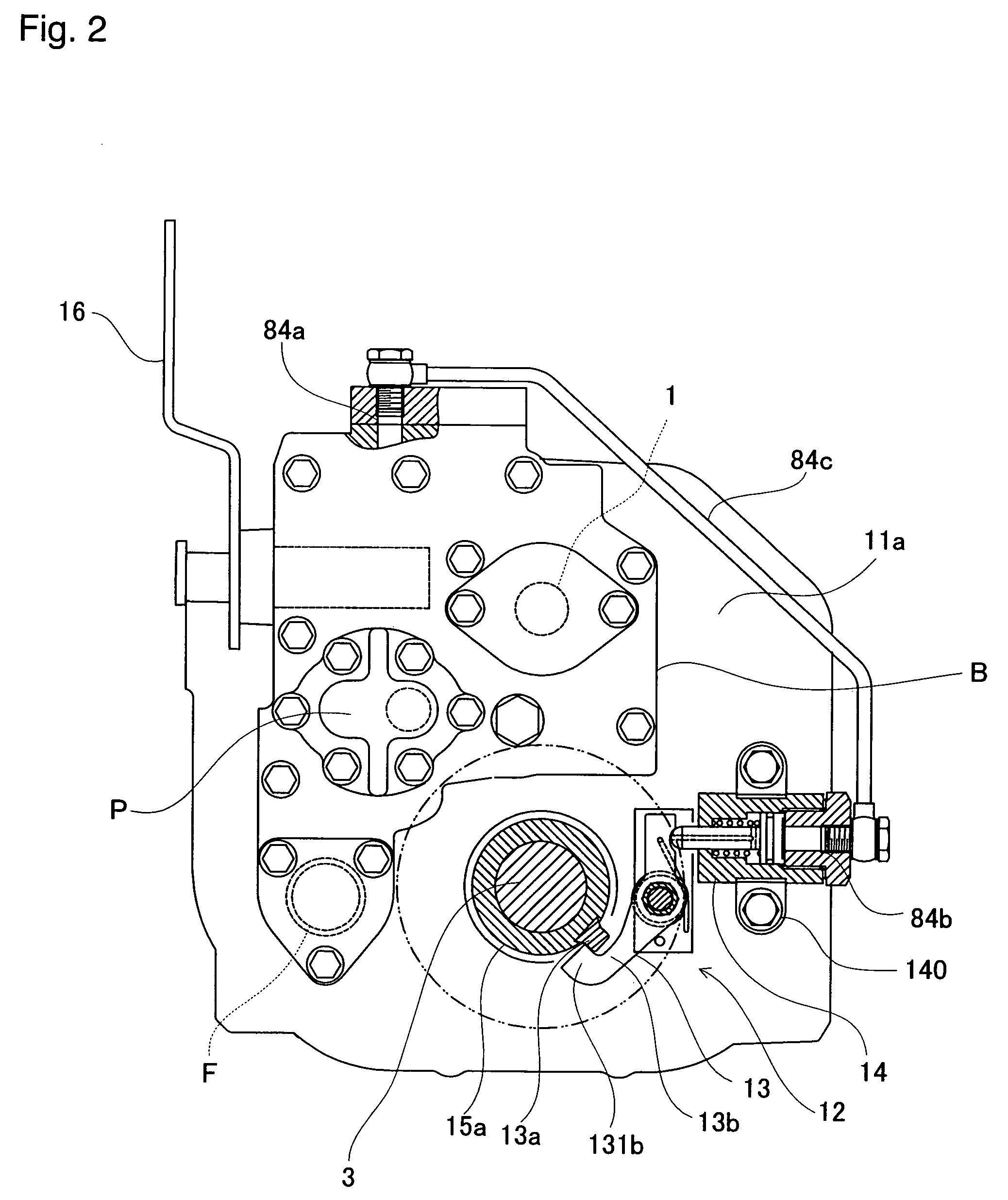
[0026]As shown in FIG. 1, the marine reversing gear assembly of the present invention comprises an input shaft 1 driven by an internal combustion engine (not shown), an input gear 2 provided on the input shaft 1, an output shaft 3 connected to a propeller shaft, an output gear 4 fixed to the output shaft 3, a forward pinion 5 that is loosely fitted to the input shaft 1 and that engages with the output gear 4, a hydraulic forward clutch 6 for coupling the forward pinion 5 to the input shaft 1, a reverse shaft (not shown) for rotating the output shaft 3 backward, a reverse pinion (not shown) that is loosely fitted to the reverse shaft and that engages with the output gear 4, a hydraulic reverse clutch 7 (see FIG. 5) for coupling the forward pinion 5 to the reverse shaft, an oil supply circuit 8 for switching to the forward clutch 6 or reverse clutch 7, and a hydraulic pump P driven by the input shaft 1.

[0027]The forward clutch 6 comprises a tubular clutch housing 6a with a bottom havi...


PUM


Abstract

A self-contained marine reversing gear assembly is provided with a locking device for an internal combustion engine in which introduction of the working oil from the lubricating oil circuit is unnecessary. The locking device includes an input shaft driven by an internal combustion engine; an output shaft connected to a propeller shaft; a hydraulic pump driven by the input shaft; a hydraulic forward and reverse clutch; a directional control valve for switching the forward and reverse clutch by the supply of working oil from the hydraulic pump; and a locking device provided with a locking mechanism member for locking the output shaft. The locking device includes a hydraulic actuator for unlocking the output shaft by operating on the locking mechanism member due to the supply of working oil from the hydraulic pump.

Description

BACKGROUND OF THE INVENTION[0001]The present invention relates to a marine reversing gear assembly disposed between an internal combustion engine and a propeller shaft. The marine reversing gear assembly transfers the driving power of the internal combustion engine to a propeller by switching the rotation direction forward and backward (reverse) while decelerating.[0002]A ship provided with a marine reversing gear assembly keeps the forward or reverse clutch engaged by supplying working oil to a hydraulic forward or reverse clutch, and rotates a propeller shaft by transferring the torque of the internal combustion engine to the output shaft through the forward or reverse clutch.[0003]When a sail-fitted ship is sailing, its internal combustion engine is stopped. Furthermore, in a ship provided with two engines and two propeller shafts, even if one of the internal combustion engines breaks down, the ship can cruise using the unbroken internal combustion engine. In this case, the prope...

Claims


Application Information

Patent Timeline
Patent Type & Authority Patents(United States)
IPC IPC(8): B60W10/02B60W10/18B63H23/30
CPCB63H23/08F16H63/3483F16H63/48
Inventor OKANISHI, TOSHIAKINAKAGAWA, SHIGEAKI
Owner YANMAR POWER TECHNOLOGY CO LTD
Learn More