Determination and selection of transmission paths as a function of the operating situation for setting up rake fingers for rake receiver units in mobile communication terminals

a technology of transmission path and operating situation, applied in the field of communication mechanisms, can solve the problems of noisy delay profile estimate, unusable allocation of rake fingers, and inability to use, and achieve the effect of more objective accuracy and flexibility

Active Publication Date: 2009-03-24
APPLE INC
View PDF21 Cites 12 Cited by
  • Summary
  • Abstract
  • Description
  • Claims
  • Application Information

AI Technical Summary

Benefits of technology

[0008]The following presents a simplified summary in order to provide a basic understanding of one or more aspects of the invention. This summary is not an extensive overview of the invention, and is neither intended to identify key or critical elements of the invention, nor to delineate the scope thereof. Rather, the primary purpose of the summary is to present some concepts of the invention in a simplified form as a prelude to the more detailed description that is presented later. Accordingly, one object of the present invention is to specify a method for determination and selection of transmission paths in a mobile communication terminal, which can be carried out more flexibly, so that the relevant transmission paths can be determined with more objective accuracy.
[0009]The present invention facilitates determination and selection of transmission paths in a mobile communication terminal. Additionally, the present invention also facilitates setting up rake fingers in a rake receiver unit for a receiver circuit in a mobile communication terminal on the basis of the selected transmission paths.
[0012]This measure makes it possible to take better account of the actual conditions for mobile radio transmission, so that the relevant transmission paths can be determined more realistically and in a shorter time. In this case, in particular, the invention provides for the capability to set up all of the parameters that have been mentioned above such that they are variable, and for the relative speed, the frequency discrepancy and the noise level to be determined continuously or at time intervals and for the parameters to be set as a function of the measured values.
[0019]It is possible for the parameters described above to be dependent on influencing variables including the relative speed, the frequency discrepancy and noise level, continuously, on the basis of a predetermined functionality. However, this would involve a relatively high degree of implementation complexity. On the other hand, it is simpler and sufficient for the purposes of the invention for the influencing variables including the relative speed, the frequency discrepancy and the noise level each to be subdivided on the basis of their magnitude into a finite number of areas, thus making it possible to produce a table of the values (defined in advance for each operating state) for the parameters NCORR Navg, Navg fading and RI. For example, in the simplest case, the influencing variables can be subdivided into two areas, specifically high or low, thus resulting in a total of eight operating states, and predetermined values for the parameters for each of these eight operating states can be stored in the table.

Problems solved by technology

However, the previously known methods for delay time estimation and path selection have ignored the instantaneous operating situation, in particular the relative speed between the transmitter and receiver, the frequency offset and the noise level.
If these parameters are set to fixed values, then this leads to noisy delay profile estimates, or delay profile estimates that are subject to errors, and, as a consequence of this, to incorrect allocations of rake fingers with unusable transmission paths, or to allocations of usable transmission paths which are not feasible.

Method used


Image

  • Determination and selection of transmission paths as a function of the operating situation for setting up rake fingers for rake receiver units in mobile communication terminals
  • Determination and selection of transmission paths as a function of the operating situation for setting up rake fingers for rake receiver units in mobile communication terminals
  • Determination and selection of transmission paths as a function of the operating situation for setting up rake fingers for rake receiver units in mobile communication terminals

Examples


Embodiment Construction

[0042]The present invention will now be described with respect to the accompanying drawings in which like numbered elements represent like parts. The figures provided herewith and the accompanying description of the figures are merely provided for illustrative purposes. One of ordinary skill in the art should realize, based on the instant description, other implementations and methods for fabricating the devices and structures illustrated in the figures and in the following description.

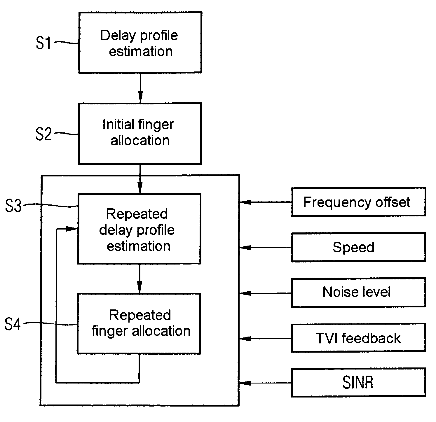
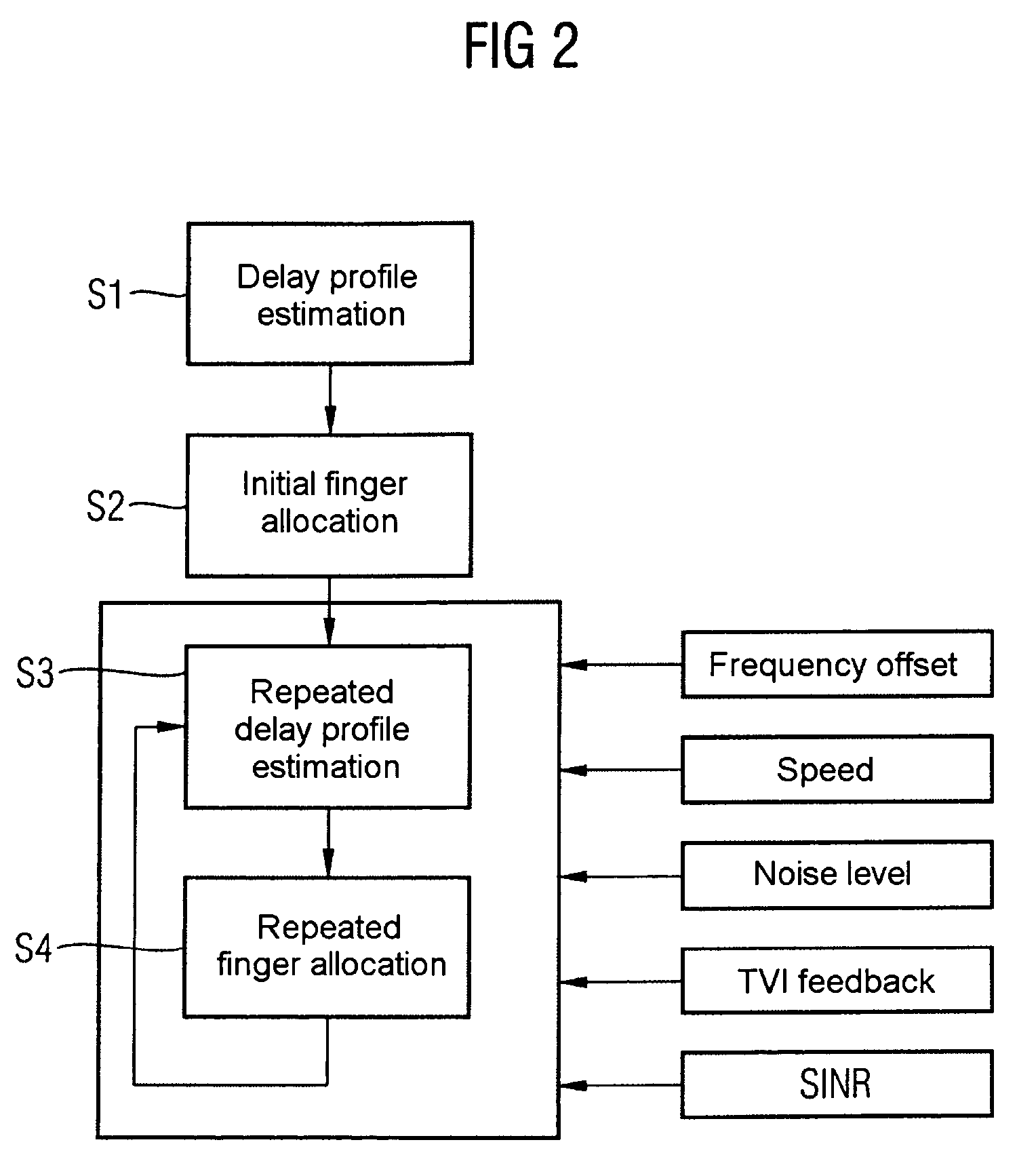
[0043]By way of example and in the form of a schematic flowchart, FIG. 2 shows a method in accordance with the present invention. An initial delay profile estimation process is carried out in a step S1 in which no measurement variables are yet available for the influencing variables, also referred to as influencing parameters, comprising the relative speed, frequency discrepancy and noise level. The delay profile estimation process is therefore carried out using preset values for the parameters for th...


PUM


Abstract

Correlations between the received signal to which pilot symbols have been applied at the transmitter end, and a correlation signal which contains the pilot symbols are carried out in the receiver in order to determine a path delay profile. Averaging processes are carried out over two or more delay profiles obtained in this way. Evaluations are carried out in one or more threshold value selection units (22.1, 22.2) on two or more averaged delay profiles with the aim of path selection. The parameters which govern the correlations and / or the averaging processes and / or the evaluations, and / or the repetition interval of these calculations are set as a function of the relative speed between the transmitter and the receiver, the frequency error between the carrier frequency of the received signal and the reference frequency that is set at the receiving end, and the noise level of the received signal. In the case of reception from two or more base stations, a final path selection is made in a finger allocation unit (40).

Description

REFERENCE TO RELATED APPLICATIONS[0001]This application claims the benefit of the priority date of German application DE 103 45 959.6, filed on Oct. 2, 2003, the contents of which are herein incorporated by reference in their entirety.FIELD OF THE INVENTION[0002]The present invention relates generally to communication mechanisms and, more particularly, to methods for determination and selection of transmission paths and setting up rake fingers in a rake receiver on the basis of the selected transmission paths.BACKGROUND OF THE INVENTION[0003]In a mobile radio, radio signals are subject to multipath propagation, that is to say a number of versions of the received signal occur in the receiver as a result of reflection, scatter and diffraction of the transmitted radio signal on various obstructions in the transmission path and these versions are shifted in time with respect to one another, and have different attenuations. The method of operation of a rake receiver is based on the idea ...

Claims


Application Information

Patent Timeline
Patent Type & Authority Patents(United States)
IPC IPC(8): H03K9/00H03D1/06H04B7/10H04B1/707H04B7/08H04B7/26H04B17/00
CPCH04B1/7113H04B1/7117
Inventor BILGIC, ATTILABOTTERO, MAUROCANONICI, JEAN-XAVIERZIMMERMANN, MANFRED
Owner APPLE INC
Why Eureka
Try Eureka