
Serial transfer interface

a serial transfer and interface technology, applied in the field of serial transfer interfaces, can solve the problems of not being able to confirm that the signal waveform has been successfully corrected by the set equalizer, it is difficult for some devices to observe a waveform, and it is difficult to achieve sufficient optimization, etc., to achieve stable and high-quality signal, easy optimization, and easy to transfer

Inactive Publication Date: 2009-03-24
FUJITSU LTD
View PDF12 Cites 26 Cited by
  • Summary
  • Abstract
  • Description
  • Claims
  • Application Information

AI Technical Summary

Benefits of technology

Enables efficient optimization of signal waveforms, reducing manual adjustments and ensuring stable, high-quality signal transmission across varying environments and LSI processes.

Problems solved by technology

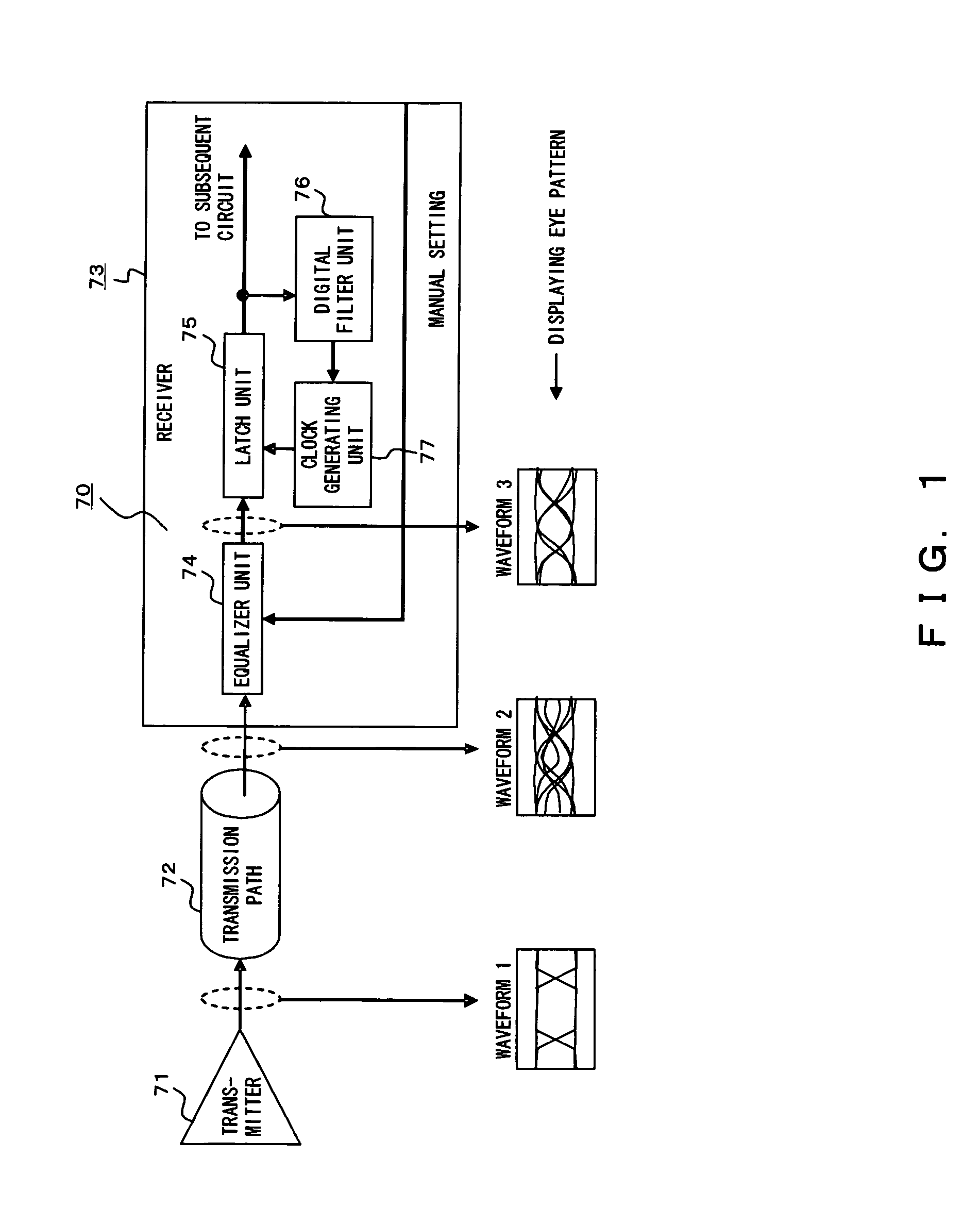
Although a waveform can be measured and the equalizer unit 74 can be optimized using only representative lanes and the connection condition of other lanes can be matched with the representative lanes, it may be difficult for sufficient optimization.
Therefore, it may be difficult for some devices to observe a waveform due to deficient space for a probe.
Therefore, it may not be possible to confirm that a signal waveform has been successfully corrected by the set equalizer.

Method used


Image

  • Serial transfer interface
  • Serial transfer interface
  • Serial transfer interface

Examples


Embodiment Construction

[0035]The embodiments of the present invention are explained below by referring to FIGS. 2 through 7.

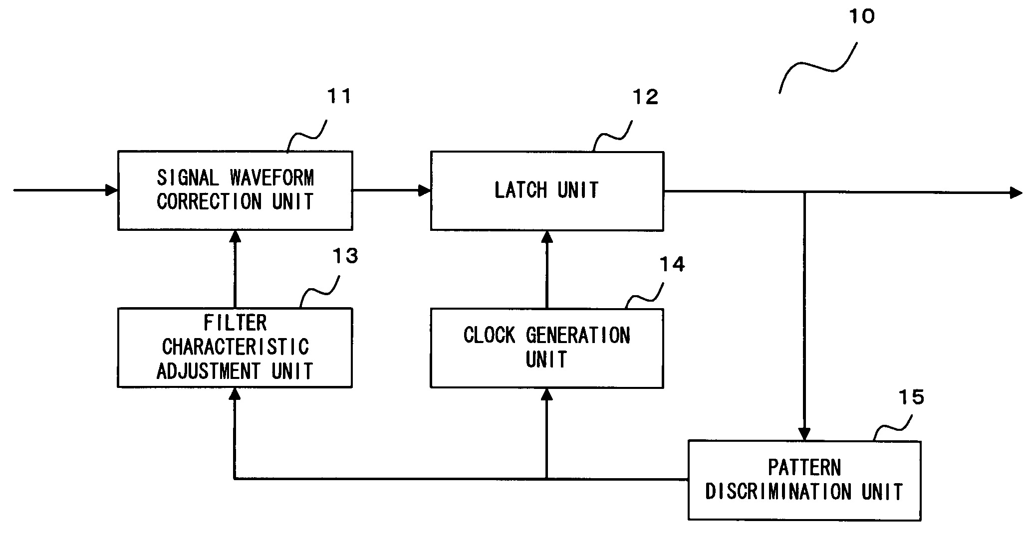
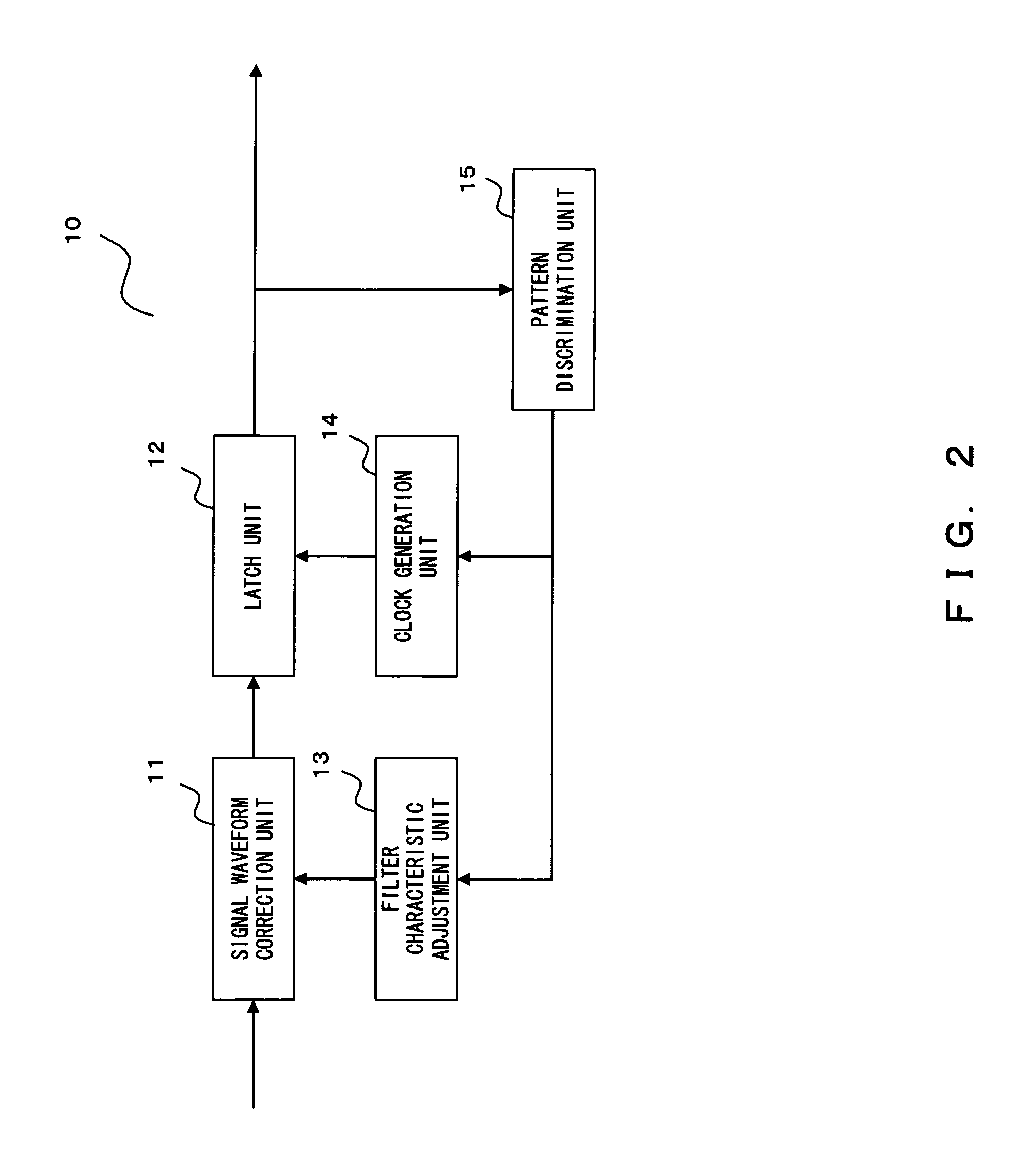
[0036]FIG. 2 is an explanatory view showing the principle of the present invention.

[0037]A serial transfer interface 10 shown in FIG. 2 includes a signal waveform correction unit 11 for correcting the distortion of a signal waveform using a filter characteristic, a latch unit 12 for latching the corrected signal waveform according to a synchronous clock and outputting the latched waveform to a subsequent circuit, a filter characteristic adjustment unit 13 for changing the filter characteristic of the signal waveform correction unit 11 in a predetermined range, a clock generation unit 14 for generating a synchronous clock having a desired phase, and a pattern discrimination unit 15 for detecting a test pattern as a test signal and controlling the filter characteristic adjustment unit 13 and the clock generation unit 14.

[0038]The signal waveform correction unit 11 corrects the distorti...


PUM


Abstract

To provide a serial transfer interface for realizing a transmission of a stable and high-quality signal although there are characteristic variances due to an environment change and an LSI process, a serial transfer interface is provided at least with a signal waveform correction unit for correcting the distortion of a signal waveform, a latch unit for latching the signal waveform with a synchronous clock and outputting it to a subsequent circuit, a filter characteristic adjustment unit for changing the filter characteristic of the signal waveform correction unit in a predetermined range, a clock generation unit for generating the synchronous clock having a desired phase, and a pattern discrimination unit for detection of a test pattern and control of the filter characteristic adjustment unit and the clock generation unit.

Description

BACKGROUND OF THE INVENTION[0001]1. Field of the Invention[0002]The present invention relates to a serial transfer interface for correcting a loss generated at a high-frequency area.[0003]2. Description of the Related Art[0004]Recently, the PCI (peripheral component interconnect) and PCI-X used in a standard interface, etc., being utilized to connect the processor bus of a personal computer or a server to peripheral equipment, are going to be replaced with a PCI express which is a serial transfer interface in order to improve the data transfer speed.[0005]Similarly, the ATA (AT attachment) used for connection of an HDD and CD-ROM to a storage device has been replaced with a serial ATA, and the SCSI (small computer system interface) has been replaced with a SAS (serial attached SCSI).[0006]In these serial transfer interfaces, a method of obtaining a more stable signal waveform is requested to use a high-frequency band by automatically correcting a loss at each frequency band.[0007]FI...

Claims


Application Information

Patent Timeline
Patent Type & Authority Patents(United States)
IPC IPC(8): H03H7/40
CPCH04L7/04H04L25/03834H04L25/03885H04L7/044H04L7/046
Inventor YAMAZAKI, MANABU
Owner FUJITSU LTD
Learn More